This page is currently being rewritten and updated as of April 2018, please do not delete yet, see talk page
This article aims to examine the design and implementation of redstone computers in Minecraft.
See chapter 1 Tutorial on Building a Computer for a detailed tutorial on building a computer in Minecraft and how to expand and improve on the example. Does not require any extensive knowledge of Computer Science. NOT FINISHED.
See chapter 2 Planning a Redstone Computer for basic computer concepts of designing and understanding a redstone computer in Minecraft. Does not require any extensive knowledge of Computer Science.
Chapter 3 is currently to be deleted.
Overview
Computers facilitate the implementation of ideas which are communicated from humans through programming.
This article will explain the basics of designing and building a computer in Minecraft, assuming the reader is fairly familiar with redstone and computers to a basic conceptualization.
All computer systems have at least one processing unit. During operation, processing units execute instructions stored in the computer's memory.
Most computers in Minecraft are made of redstone, redstone torches, and repeaters, leading into sticky pistons or redstone lamps which are controlled using a series of buttons, levers, pressure plates, etc.. Other proposed ideas (not covered) are to use hoppers, mine carts or boats with redstone.
See chapter 2 Tutorial on Building a Computer for a detailed tutorial on building a computer in Minecraft and how to expand and improve on the given example. Does not require any extensive knowledge of Computer Science as it will be explained.
See chapter 3 Planning a Redstone Computer for basic computer concepts of designing and understanding a redstone computer in Minecraft. Does not require any extensive knowledge of Computer Science although will delve quite deep into it.
Implementations
Computers can be used in many ways, from creating a smart house to using it to run a whole city. It could also be used in mini-games, as it can store info about who has the high score, and calculate if it is possible to beat this score. The uses of a computer are almost infinite. Please note that due to their extremely slow speed, as well as their large size, redstone computers are difficult to find practical applications for. Even the fastest redstone computers take seconds to complete one calculation and take up many blocks worth of space.
However, mods which change your tick rate such as TickrateChanger will significantly speed up the computer's speed, as well as Minecraft.
Chapter 1: Tutorial on Building a Computer
Introduction
Redstone logic closely reflects binary logic, as redstone can be either on or off, and can, therefore be interpreted as 1s or 0s. The reader must be familiar with at least a basic understanding of binary and the conversion of denary to binary (base 10 to base 2). There is an excellent article which explains that. Please read the Architecture of building the Computer section as we will be following that plan, it is located in this article, thank you.
This chapter will focus on the application of the knowledge and manipulation of redstone to create a simple 4-bit computer. 4 bits means the computer will be able to count up to the number (2 ^ 4 - 1) = 15, having four channels on their bus. A computer of this scale is not very capable of large tasks, and can only execute very simple instructions and on the contrary, an 8-bit computers can count to the number (2 ^ 8 - 1) = 255 and are therefore more practical for basic programs such as the Fibonacci sequence of Fizz buzz. More about this in the third chapter of this article. So why a 4-bit computer? Choosing to build a 4 bit computer is a decision to allow for you to understand the basic concept of computer design and its integration with Minecraft, and how you can expand on these ideas and customize a computer suitable for your needs - it also avoids any confusion with more complex tasks the computer can do, it is best to start walking before running.
This is why you can only increment to 15 on a 4 bit computer.
| 8 | 4 | 2 | 1 | denary |
|---|---|---|---|---|
| 0 | 0 | 0 | 0 | = 0 |
| 0 | 0 | 0 | 1 | = 1 |
| 0 | 0 | 1 | 0 | = 2 |
| 0 | 0 | 1 | 1 | = 3 |
| 0 | 1 | 0 | 0 | = 4 |
| ... | ||||
| 1 | 1 | 1 | 0 | = 14 |
| 1 | 1 | 1 | 1 | = 15 |
...adding another one would only loop it back and it would return 0.
There are three primary design objectives for a computer in Minecraft, to make your computer most suitable for your task of design.
- Compactness
How small is the computer? Real life computers will also worry about power usage if they worry about compactness, as they are most likely designing a laptop. In Minecraft, designing a survival computer will most likely emphasize on this point
- Memory
How much memory can it hold? How many bits and numbers it can count up to? The is important for large-scale computers, say ones which can recite the alphabet at least needs to remember the alphabet, and words.
- Speed/Performance
How fast can it do operations? Is it optimized to run its tasks? Custom designing and building a computer will significantly increase its speed as more redundant wiring and code could be switched to purpose-built hardware and software. This is apparent in some real-world supercomputers which are programmed to run one task very, very efficiently. The speed of computers in Minecraft is very slow, therefore a mod, such as TickrateChanger could be installed for the client to significantly increase the speed of the game, and therefore the computer.
Building an Arithmetic Logic Unit
The Arithmetic Logic Unit referred to as the ALU will compare and perform mathematical operations to binary numbers and communicate the results with the Control Unit, the central component of the computer (and Central Processing Unit but that is going to be as big as the computer itself). Many tutorials will want the reader to build an ALU first, and therefore is covered very widely around the internet.
The ALU we will be building can perform four important operations on two inputs and return a correct output. A, B, being both 4-bit inputs
- A+B (Add A to B)
- A-B (Subtract B from A)
- A>B? (Is A more than B?)
- NOT A (The opposite of A)
Albeit used for more powerful computers, there are other commands that demand more of the ALU; e.g. incrementing or decrementing A or B by one, or perform no operation at all. There can also be multiple ALUs inside a computer, as some programs require many operations, which do not depend on the previous operations and delegating the commands to different ALUs could significantly speed up the process.
binary adder
Adding a number
In an adding unit, for each bit (for our computer, we require four, hence 4-bit), there is a full adder. The full adder will take three inputs, each input can be either 1 or 0. The first two will be the user's input and the third will be the carry input. The carry input is the output of the previous full adder, this will be explained later. The adder will output two statements: first, the output and then the carry output, which is sent as input into the next full adder, a place value up.
For example, I wish to add the number 0101 to 1011. The first full adder will consider the first place value, 1 and 1 as their two inputs (we are reading right to left). There is no carry input as there is no previous full adder. The full adder will add 1 and 1; which is 0, and carries a 1 to the next place value. The next full adder would add 0 and 1 and the carry input would be 1 which the previous full adder stated. The output of 0 and 1 would be 1 but there is a carry input of 1 and therefore will add 0 and 1 and 1, which is 0 and carries a 1 to the next place value. Reviewing addition in binary should resolve any confusion.
full binary adder
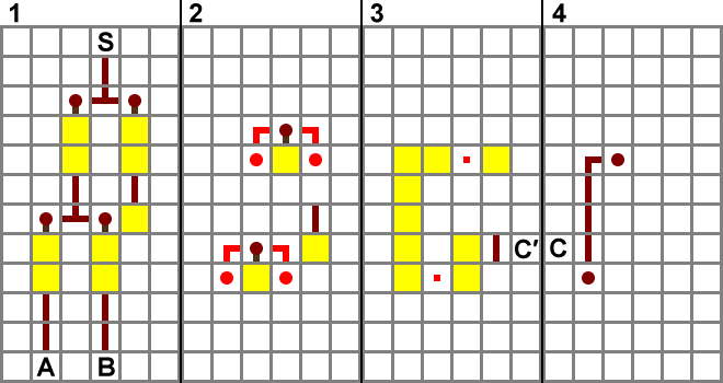
All ALUs, to perform adding operations require the presence of multiple adders. Each two bits will feed into an adder which when joined with other adders, will produce an output which is the sum of the two bytes added together. An adder has an input, an output and two carry input/output as would a person carry when doing the addition of 9 + 1 or 01 + 01. The adders are made of logic gates which is possible by the nomenclature of binary. Tutorials/Advanced_redstone_circuits gives a very detailed look into full adders and half adders, for now, there is a schematic of how to construct one. It gives four inputs/outputs and should be connected with other adders to create a unit. For this example, we will connect four adders together in our four bit computer so that we can take in all four bits to make an output. There will be an input carry missing from the first adder, this is because there is nothing to carry from the bit before it, it is the first bit. The input carry will remain at zero. There will also be an output carry missing from the fourth adder, and the output of this will be ignored as we can only support four bits. The additional carry output will be too much and if it is on, is a specific error called a binary overflow.
So basically, go into Minecraft and build a full binary adder (picture show) and connect them up. There should be eight inputs and outputs. Try placing levers and redstone lamps at the respective end to test your creation. So 0010 + 0011 should yield 0101 (2 + 3 = 5, we are reading right ot left).
Fractional numbers
A computer takes care of numbers less than one by forms of float-point arithmetic, it is only so useful in larger-bit computers (16-64 bits) and computers which do need to use numbers less than one. https://en.wikipedia.org/wiki/Floating-point_arithmetic or https://www.geeksforgeeks.org/floating-point-representation-digital-logic/ are two ways to achieve this. Another simpler but less efficient way would be to assign all numbers a power of two so that they are 'bumped up' by the power of two you chose. You must do this to every number and assume the one as one times the power of the two you have chosen. For example, 5 = 101 so 5 * 2^3 = 101000; five is bumped up by three. So now, one in your new system would be 1 * 2^3 = 1000 and that would leave room for 0.1, 0.01 or 0.001; 0.01 * 2^3 = 10. This leads to a more complicated setup for your computer.
Chapter 2: Planning a Redstone computer
A redstone computer can be planned very much like a real computer, following principles used in computer design and hardware architecture. There are several key design decisions that will affect the organization; size and performance of your prospective computer should be made concretely prior to the construction of specific components.
Building a redstone computer will require the understanding of these five concepts and consider the most suitable approach, which would be most practical for your computer.
- Machine-Architecture (Components of a computer, what are they and what they do)
- Execution Model (The organization of components, making them efficient)
- Word-Size (How many bits the system uses. Usually, powers of 2, around 4, 8, 16 bit is normal in Minecraft)
- Instruction Set (The instructions to be performed by the CPU).
and we will be applying this knowledge and plan the architecture of our CPU in the last section. This CPU will then be built in the next chapter.
Machine-Architecture
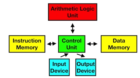
There are five components which are vital to creating a computer. It is best not to show their Minecraft counterparts as there is a very large variety of methods to design each component and would not aid the understanding.
five components of a computer
Arithmetic Logic Unit (ALU)
- Perform adding and subtracting
- Compare booleans using logic gates
Control Unit (CU)
- Perform/Execute instructions sent to it
- Communicate with all components
Data Memory
- Store and return data from storage devices
Instruction Memory
- Return instructions, sent to the CU
- Can be set, but doesn't need to be as often as the Data Memory
Input/Output devices (I/O)
- Allows the computer to communicate with the world and the player.
- Can input information the computer (button push, daylight sensor)
- Can output information from the computer (redstone lamp, note block)
Storage Devices
There are a large variety of storage techniques, although there is an inverse relationship to the device's read/write speed and its size. More prominently, increasing the device's capacity would increase its size.
In a computer, there are three types of storage. This is because of each type would have a speed and capacity appropriate to it.
Registers & Flags
Fastest, are the memory within the CPU. These are registers and flags as they can be set almost instantaneously and do not require any address sent to it as there is only one place in each register to remember the data.
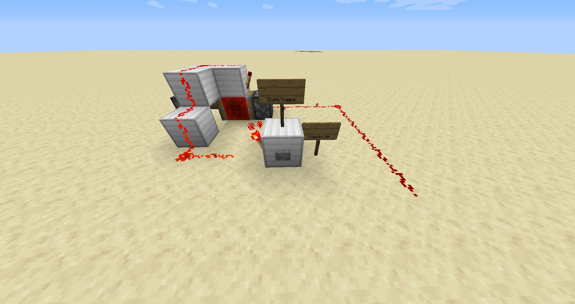
Redstone bits which can be toggled is extremely large but can be toggled within 2 ticks. This requires a very large amount of space but is perfect for caches and registers. The redstone is also required for logic gates (not shown) to set the bit, as in the images, sending an input would cause the bit to flip. The gate would take up more space. Registers could also utilize locking redstone repeaters and timing them correctly. This is explained below, in RAM). With the use of a computer clock, it may not be necessary to build registers. Registers are useful for when the data goes through the line before either the CU or ALU is ready to process it. It would save it to the register and wait until the CU or ALU can perform its function.
Caches
Second to that are caches, which feed into the processor. In real life, they are separated into levels, each one with separate speed and capacities.. It is useful for the same reason as the registers.
Random Access Memory (RAM)
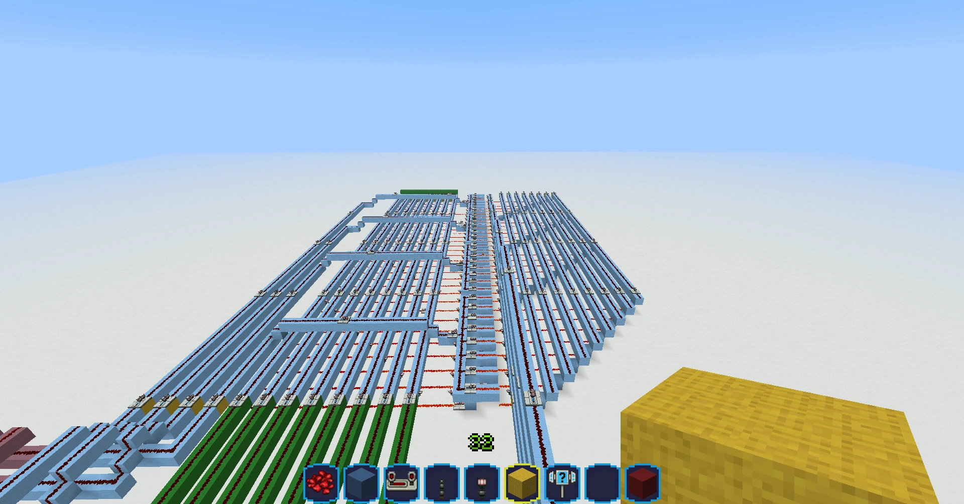
Thirdly is Random Access Memory (RAM), this is much slower than the caches and registers as they have address systems. They are connected to three busses, data bus, control bus and the address bus. The data is sent through the data bus, either setting the RAM or getting values from the RAM. The control bus tells it whether it is being get or set. The address bus tells the RAM where the byte is. Refer to the Architecture of the Computer to understand this more in-depth. RAM is very useful and could fully replace tertiary memory (explained below) because of its non-volatility in Minecraft. Volatile means that when power is lost, it will lose information. The RAM will not lose information unlike in real life, and therefore in an excellent method of storing information.
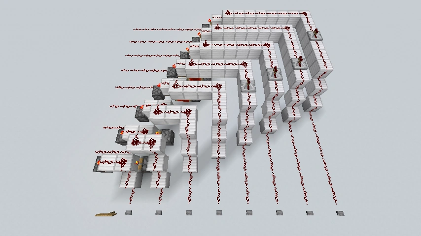
The RAM in the first case is utilizing the locking redstone repeaters with correct timing. This requires a bit of a plan but is very space efficient. The conversion of a bus to the lines in order to lock the redstone repeaters also requires setting timings. This is time-consuming, much more than the registers, however, is very compact and efficient. The address bus (green) would turn in binary to unlock a certain byte, either to be read or set by the control bus (second line, on the left).
Most often, making it volatile has no use in Minecraft, so the easiest way to make some is to use d-flip-flops and to add a reading and writing function. The bottom image shows instead of locking repeaters, it uses d-flip-flops which is much more space inefficient but simpler to build. D-flip-flops work more or less like locked repeaters, one input - if on, unlocks in until the input is off and the other will set it once unlocked. The output can be read as a bit and with a NAND gate, be ignored or put onto the bus. This is gone over in detail in the second chapter, Tutorial on building a Computer. Excuse the texture pack.
Random Access Memory also know as RAM is a kind of memory used by programs and is volatile. Volatile means that when power is lost, it will lose information. Most often, making it volatile has no use in Minecraft, so the easiest way to make some is to use d-flip-flops and to add a reading and writing function.
Tertiary Memory
Fourth and last, is a Tertiary memory, which requires a lot of time to read/write but can hold massive amounts of information at the expense of speed. There is a very compact storage technique, involving redstone comparators with the ability to store up to 1KB, being practically sized. The read/write speed is fairly slow due to the massive amount of comparators and a lot of time is required. Aforementioned mods could speed up tickrate and eliminate this problem, however. This is used for storing long-term data which needed to be loaded at the beginning of a program or rarely due to its poor read/write speed and large capacity. This is the equivalent of a real computer's hard disk or solid-state drive.
Execution Model
The technique of storing blocks of instructions called programs within memory is what allows computers to perform such a variety of tasks.
The apparatus employed by a computer for storing and retrieving these programs is the computer's Execution Model.
Two of the world's most successful Execution Models, Harvard and von Neumann, run on nearly 100% of the computers available today.
This is more advanced, and is for inquisitive and curious readers
Harvard
The Harvard architecture physically separates the apparatus for retrieving the instructions which make up an active program from that of the data access apparatus which the program accesses during execution.
Programs written for computers employing a Harvard architecture may perform up-to 100% faster for tasks which access the main memory bus. Note however that certain memory circuitry is necessarily larger for those who select a Harvard architecture.
von Neumann
The von Neumann architecture uses a two-step process to execute instructions. First, the memory containing the next instruction is loaded, then the new instruction just loaded is allowed to access this same memory as it executes; using a single memory for both program and data facilitates Meta-Programming technology like compilers and Self-modifying Code.
The von Neumann architecture was the first proposed model of computation and almost all real-world computers are von Neumann in nature.
Word sizes
Word-size is a primary factor in a computer's physical size.
In Minecraft, machines from 1-bit all the way up to 32-bits have been successfully constructed.
Common word-size combinations :
| Data | Instruction |
|---|---|
| 4 | 8 |
| 8 | 8 |
| 8 | 16 |
| 16 | 16 |
Data-Word
The amount of information a computer can manipulate at any particular time is representative of the computer's Data Word-size.
In Digital Binary, the computer's Data-Word size ( measured in bits ) is equal to the width or number of channels in the computers main bus.
Data-Words commonly represent integers or whole numbers encoded as patterns of binary digits.
The maximum sized number representable by a Binary encoded integer is given by 2 ^ Data-Word width in bits - 1.
For example, a computer with a Data-Word size of 8-bit will have eight channels on its bus (set of wires, connecting components) 8-bit bus and therefore, we can count up to (2 ^ 8 - 1). 255. Counting further than 255 is not possible with eight bits, as the operation 255 + 1 carries over a one, which requires a ninth bit or what is called a binary overflow will occur, returning 0 as the answer, which is incorrect.
This is simply visualized;
| 1 | 1 | 1 | 1 | 1 | 1 | 1 | 1 | 255 | |
| + | 0 | 0 | 0 | 0 | 0 | 0 | 0 | 1 | 1 |
| = | 0 | 0 | 0 | 0 | 0 | 0 | 0 | 0 | 0?! |
Some common Integer data sizes are:
| Max Representable Number | Number of Bits Required |
|---|---|
| 1 = ( 2 ^ 1 - 1 ) | 1 |
| 7 = ( 2 ^ 3 - 1 ) | 3 |
| 15 = ( 2 ^ 4 - 1 ) | 4 |
| 255 = ( 2 ^ 8 - 1 ) | 8 |
| 65535 = ( 2 ^ 16 - 1 ) | 16 |
| 4294967295 = ( 2 ^ 32 - 1 ) | 32 |
Data-Word size also governs the maximum size of numbers which can be processed by a computer's ALU (Arithmetic and Logic Unit).
Instruction-Word
The amount of data a computer needs in order to complete one single instruction is representative of a computer's Instruction Word-size.
The Instruction-Word size of a computer is generally a multiple of its Data-Word size, This helps minimize memory misalignment while retrieving instructions during program execution.
Instruction Set
This is a collection of instructions the Control Unit (CU) can decode, and then execute.
Instructions are essentially functions run by the computer, examples of instructions include:
- Add, subtract, multiply and divide
- Read/Write from RAM/ROM/tertiary memory
- load and unload data into the RAM
- Branching to other parts of the code
- Comparing registers
- Selecting a Logic function (NAND, NOR, NOT etc.)
Instructions can be programmed into the RAM, loaded from ROM or directly activated by using a lever or button. Each instruction would have its own specific binary string assigned to it (e.g. 0000=Load data from register 0001=add A and B 1011=Save RAM into tertiary memory etc.) and would probably require its own binary to decimal or binary to BCD to decimal encoders and buses to the ALU/registers.
Architecture of the Computer
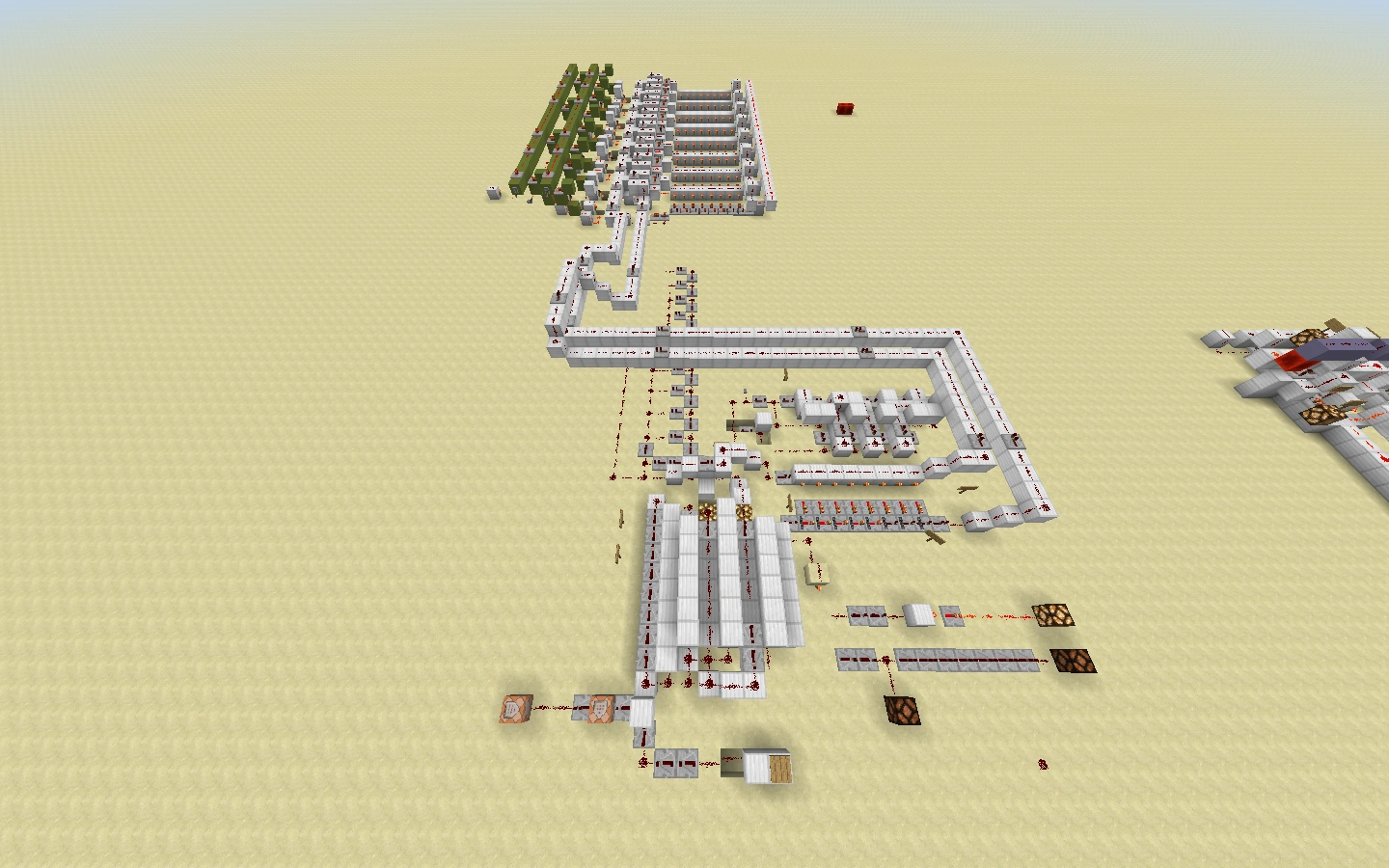
Inside the computer, there is a Central Processing Unit (not to be confused with the Control Unit (CU), a component inside the CPU), which in real life, is a very small and powerful component which acts as more or less, the brain of the computer. In Minecraft, it is difficult to compact it to the scale we see in real life so don't worry if it looks wrong.
We will first be designing our 4-bit Central Processing Unit in the next chapter, as it is the most important thing in our computer with the Execution Model (the method of communication and organization of the CPU) in mind, (talked about in this page, before, in the Execution Model section) we can map out the construction of the computer.
Map of the CPU, based on the Havard Execution Mode
The CPU follows a cycle four steps, fetch, decode, execute and (sometimes) stores to perform instructions. The CPU first fetches the instruction from RAM, decodes what it means (the instruction will most likely be a number, and the CPU must find out what number it is), and once it understands what the instruction is, it will perform that action. This sometimes requires for the data to be put back into the storage, therefore it will store the data. The cycle is then repeated.
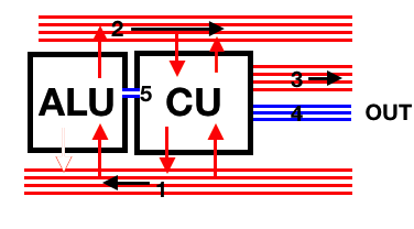
Busses
There are five busses in the CPU, each to carry information from one component to the next. Busses are channels of redstone connecting each component. Since we are building a 4-bit computer, we only need four channels in our bus. These are the red and blue lines connecting the components inside the CPU. Notice that the blue buses have less than four lines, this is because they do not carry data. Since busses can only carry data one way (in Minecraft, due to repeaters only working one way), there are two buses connecting the CPU to the outer computer.
The first bus is the data bus, this is to transfer information from the storage or I/O devices to the CU. Instructions are also sent through this line The CU can also use this bus to transfer data to the ALU. The ALU cannot transfer data onto this bus because buses only work one way and once the information is taken by the ALU, the bus cuts off beyond the ALU. Information from the ALU is passed through bus 2.
The second bus is the data bus, but returns the data from the ALU to the CU. The CU cannot send data through this bus to the ALU because the bus goes from left to right and works in one direction only. The CU can send information back to the storage units though, and is used to set values of storage devices.
The third bus is the address bus, which the CU can send the address of storage. This is where the information resides. For example, the CU asks for the address of the byte living in 0001. It sends the address (0001) through the address bus and the RAM will return the value of the byte through the first bus. 0001 is the location of the byte, not the value of it.
The fourth bus is the control bus, which the CU will communicate with the RAM with. For example, one wire could tell the RAM to set the byte to the value to the data sent to it by the CU. Another wire could tell the RAM to get the byte from the address sent to it by the CU.
The fifth bus is another control bus, linking with the ALU, which sends flags from the ALU. Flags are notes which could be error messages. For example, the CU could ask the ALU to add 15 and 1 in a 4-bit system. Adding 15 and 1 in 4 bits would yield 0 (explained above) and this is called a binary overflow. This is an error and the ALU will tell the CU about this through the fifth bus as a flag. The CPU could also send data to the ALU and ask for it to perform an action with that data.
Components
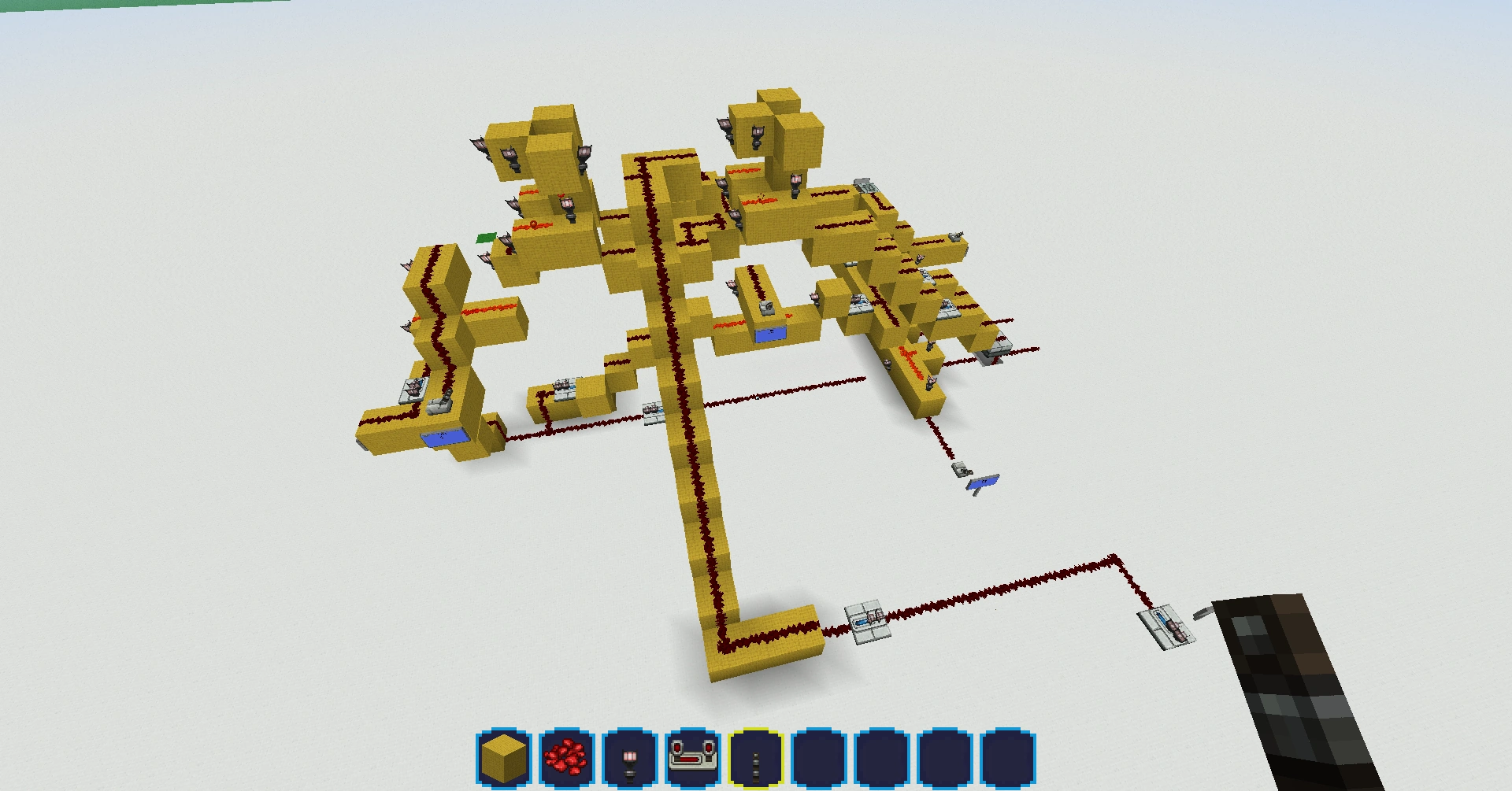
Control Unit (CU) will fetch instructions from the instruction ROM (for other computers, instructions can be changed and therefore is RAM. For our case, we are running a fixed program and do not need to change the instructions. This simplifies the process entirely and the instruction is Read-Only Memory (ROM)). Inside the CU, it will then decode the instruction, which is normally a number, into a sensible action. It will then perform that action and if the instruction requires, store the result into the RAM. It communicates with the RAM through the control bus and receives flags from the ALU. It can also ask the ALU to perform actions on data it sends to the ALU (e.g. addition). To communicate with the RAM, for example, one wire could tell the RAM to set the byte (the location of it is specified through the third, address bus) to the value to the data sent to it by the CU through the second, data bus.
Arithmetic Logic Unit (ALU) will execute instructions sent to it from the CU and will compare binary numbers and communicate with the Control Unit. It can do simple addition and subtraction which can be repeated to do multiplication and modulus (then division). There are also logic gates for booleans, the fundamental logic gates are required, such as the NOT gate and the NAND gate.
Now we can choose from a range of designs of busses, each contributing to the aforementioned three key designing goals of a Minecraft computer.
Chapter 3: Designing a Computer
Instruction-Set-Architecture
States
Memory is a set number of bits. In Minecraft, memory usually holds 8 or 16 bits, though 32-bit memory computers have been successfully built before. Each bit is in one of two possible states: on or off. Memory is a series of these on and offs, which can be used to perform certain tasks.
Symbols
Real-world computers use binary, which is a series of 1s and 0s. "1" means "on" and "0" means "off". In Minecraft, the best representation is redstone dust: having a signal means "1" and no signal means "0". However, depending on how far away the redstone is from the memory storage, it is possible for "0" to be anything from signal strength 0 all the way to 14. You can also design things to make "1" equal anything from signal strength 1 to 15.
Numbers
Our normal decimal system is a number system in base 10. Binary, the number system within computers, is in base 2. To compare, take a look at the 2-digit number. In decimal, the left digit is the 10s digit. In binary, it is the 2s digit. For example in decimal, "10" is read as "ten". In binary, "10" is read as "two". There are two commonly-used methods of converting from decimal to binary:
Highest Bit First: This method requires a bit of intuition. Let's use 42 as an example. We first start by looking for the largest exponential of 2 (e.g. 32 [2^5] or 65536 [2^16]). In this case, it's 32. We then subtract that number from the number in question. 42-32=10. Also, the very first bit from the left is a "1". We then step down to the next exponential of 2 and see if it is less than or equal to our current number. For this example, the next one is 16. 16 is not less than 10, so the next bit is "0". We keep doing this until the number reaches 0. Whenever the 2 exponential is less than or equal to the number, subtract them and the next bit is "1". If not, the next bit is "0". To continue our example: 8<10-->10-8=2-->"1" 4>2-->"0" 2=2-->2-2=0-->"1" 1>0-->"0" So our final binary representation of 42 is "101010". Fancy.
Lowest Bit First: This method requires no memorization of 2 exponentials. Instead, it repeatedly divides the number by 2, using the quotient as the next number, and the remainder as the binary bit. Keep in mind, though, that this method writes the binary number from right to left, as opposed to the previous method which wrote it from left to right. Let's reuse our example, 42. 42/2=21 r 0 (rightmost bit is 0) 21/2=10 r 1 (next bit to the left is 1) 10/2=5 r 0 (next bit to the left is 0) 5/2=2 r 1 (next bit to the left is 1) 2/2=1 r 0 (next bit to the left is 0) 1/2=0 r 1 (next bit to the left is 1)
Quotient is 0, so we stop. This gives us our binary number as "101010". Same as the previous method.
Transitions
Words
Instructions
Instructions are essentially functions run by the computer, examples of instructions include:
- Add, subtract, multiply and divide
- Read/Write from RAM/ROM/tertiary memory
- load and unload data into the RAM
- Branching to other parts of the code
- Comparing registers
- Selecting a Logic function (NAND, NOR, NOT etc.)
Instructions can be programmed into the RAM, loaded from ROM or directly activated by using a lever or button. Each instruction would have its own specific binary string assigned to it (e.g. 0000=Load data from register 0001=add A and B 1011=Save RAM into teritary memory etc.) and would probably require its own binary to decimal or binary to BCD to decimal encoders and buses to the ALU/registers.
Classification
Abstraction
Mapping
Symbols
Numbers
Functions
Formalization
Computability
Variables
Variables are numbers, strings (sets of characters) or booleans (true or false) stored in RAM for the purposes of running a program. For instance, booleans can be used to keep information for if the program has reached a certain state. The following information needs to be kept about a variable: Its name, type (number, string or boolean), and value. A variable's value can, as its name suggests, change. Operations can be done on variables. Variables are created while running the program and deleted from memory once the program closes. When a program is re-opened, the variables are re-created. It is the same in Minecraft.
Hierarchies
Memory
Memory is where data for programs are kept. It is volatile (It is deleted when the computer is turned off) and is used for the program to store data. For example, in a program which counts up from 1, 1 is saved to memory, 1 is loaded from memory and 1 is added to it to get 2.
Execution
Semantics
Data
Data is the information being processed by the computer and is represented using binary.
Control
Machine-Architecture
Data paths
Processing
Arithmetic Logic Unit
The ALU is one of the most important components in a computer, both in real life and in Minecraft. First, you must choose the functions you want to be able to achieve. Most often, those are addition, subtraction and a set of logic options such as AND, OR, NAND and the likes. You must then build the unit with all the logic gates and math functions you want and a way to choose which one's output to display.
Busing
Busing is what allows the components of your computer to communicate with each other. A bus can be created by using redstone wiring to connect your computer's ALU, RAM, ROM and registers together so that they can send data between each other. It is usually important to plan where to build the components of your computer so that you won't have to create busing wires too long, or even worse, have no space to create busing, in which case you can remove the offending component and rebuild it an appropriate location, or use a mod like WorldEdit to move the component somewhere else.
Storage
Random Access Memory
Random Access Memory also know as RAM is a kind of memory used by programs and is volatile. Most often, making it volatile has no use in Minecraft, so the easiest way to make some is to use d-flip-flops and to add a reading and writing function. Making one is simple. You can make 1 flip-flop and then just stack it for as long as needed, with one block taken of each byte. See the following plan for help:
(Redstone schematic to be done) Reference the picture if not sure (click on it to get it larger) r=wire p=repeater b=block t=torch on side of the block 0=air
Layer 1
00trb00
rpb0tr0
Layer 2
0b0t00b
tbbbbtb
Layer 3
0r0t00r
0rprr0r
Tertiary memory
Tertiary memory is used to compactly store large amounts of data at the expense of speed. This kind of memory consists of the database, where all the data is actually stored, and a physical mechanism, usually a robotic arm, that must physically move around the database to fetch data. For this reason, it is extremely slow and is only used for information that is rarely accessed. This is the equivalent of a real computer's hard disk or solid-state drive.
In the latest versions of Minecraft, it may be possible to create tertiary memory with sticky pistons combined with slime blocks, which can create "ships" that move around, and presumably store a Redstone component that can extract, read, and write from a wall of conducting and non-conducting blocks.
Machine State
Program Counter
The program counter is used to keep track of which line of code the computer should be reading from. During each clock cycle, the decoder will access this counter in order to fetch the next instruction to be executed. Some instructions will access a different amount of data than another or no data at all, so the decoder will in turn increment the program counter by the appropriate amount to the next instruction. The counter is also used by jump instructions to control program flow.
In real life, this counter isn't a component by itself and is simply a register right next to all the other ones. In Minecraft, however, it may be less confusing to create a separate register apart from the others to store program counter data.
Control paths
Processing
Control Unit
The control unit is the section of the computer that interprets the instructions, and controls the other parts of the computer, such as telling the ALU whether to add or subtract.
File:Redstone Computer Control Unit.PNG
Busing
File:Redstone Computer Control Busing.PNG
Storage
File:Redstone Computer Tertiary Memory.PNG
Program Memory
File:Redstone Computer Program Memory.PNG
Program memory is, most basically, ROM (Read-only Memory). ROM is most often used to perform a series of task remotely (such as a program, hence the name). It can be made to be used on user control (as in the picture) or with a clock and sufficient delay between each line so 2 aren't on at the same time. One of the simplest and most efficient design is the one in the picture, which may or may not be coupled with a decoder. It can be enlarged easily, which is another advantage.
Machine State
File:Redstone Computer Machine State.PNG
Program Counter
Clock
File:Redstone Computer Clock.PNG
Redstone clocks are used to synchronize components or to time them. In most (Minecraft) cases, it is possible to avoid the use of one but sometimes it is necessary for the computer's functioning. It can be either made from redstone torches in basically a line/circle of NOT gates (an odd number is recommended or your output will have to be NOT'ed), or from repeaters, as shown in the picture above.
Tips
- You may want to use mods like WorldEdit
- If you're in survival and don't have any repeaters you can use two Redstone torches
- Color code your computer (use blue wool for RAM, yellow for the ALU, etc.)
- Start small, and get the hang of small computers before you try more complex machines.
- Structure blocks can be very helpful for moving components around, and combining multiple components together. However, note that these cannot be obtained without using commands.
See also
- Redstone
- Redstone circuit
- Redstone clock
- Logic circuit
- Memory circuit
- Pulse circuit
- Transmission circuit
- Tutorials/Advanced redstone circuits
- Tutorials/Calculator
- Tutorials/Printing
- Tutorials/Redstone machines
- Tutorials/Telegraph