Jamtheman10171532@legacy41471968 (talk | contribs) mNo edit summary |
(rv : Those are pulsars / clocks.) |
||
| Line 1: | Line 1: | ||
[[File:ComboLock.png|thumb|427 px|A combination lock circuit.]] |
[[File:ComboLock.png|thumb|427 px|A combination lock circuit.]] |
||
| − | Redstone circuitry is a feature that was added to Minecraft in the first Alpha update. The concept allows for advanced, more-complicated [[mechanisms]] to be created by players. [[Redstone]] circuitry is commonly compared to [http://wiki.garrysmod.com/?title=Wire_Addon WireMod] (a widely-used addon from [http://store.steampowered.com/app/4000/ Garry's Mod]). |
+ | Redstone circuitry is a feature that was added to Minecraft in the first Alpha update. The concept allows for advanced, more-complicated [[mechanisms]] to be created by players. [[Redstone]] circuitry is commonly compared to [http://wiki.garrysmod.com/?title=Wire_Addon WireMod] (a widely-used addon from [http://store.steampowered.com/app/4000/ Garry's Mod]). |
==How it Works== |
==How it Works== |
||
| Line 13: | Line 13: | ||
* Wires transmit their power state to adjacent wires at the same level or up or down one level, except if the destination wire is separated from the source wire by a block above. |
* Wires transmit their power state to adjacent wires at the same level or up or down one level, except if the destination wire is separated from the source wire by a block above. |
||
| − | ** Wires only transmit their power 15 blocks from the source. |
+ | ** Wires only transmit their power 15 blocks from the source. |
* Active torches, switches, and buttons; blocks directly above active torches; and blocks with active switches or buttons attached to them will power any adjacent wires in any direction (including above and below). |
* Active torches, switches, and buttons; blocks directly above active torches; and blocks with active switches or buttons attached to them will power any adjacent wires in any direction (including above and below). |
||
* Switches attached to the top face of a block may or may not power the block, since they can face either of two directions on the ground. Switches which face east (when on) and west (when off) will power the block below them; those which face north (when on) and south (when off) will not. |
* Switches attached to the top face of a block may or may not power the block, since they can face either of two directions on the ground. Switches which face east (when on) and west (when off) will power the block below them; those which face north (when on) and south (when off) will not. |
||
| Line 66: | Line 66: | ||
====Repeater==== |
====Repeater==== |
||
[[File:NOT gate strings.gif|thumb|219px|Strings of NOT gates, used in clocks and delays.]] |
[[File:NOT gate strings.gif|thumb|219px|Strings of NOT gates, used in clocks and delays.]] |
||
| − | Using two NOT gates in series can extend your running wire length past the original 15. As of 1.0.2 (the [http://notch.tumblr.com/post/776816446/minecraft-alpha-version-1-0-2-01 July 6th update]), there must be a strip of wire between the two NOT gates. This makes it possible to send long-distance signals to doors, tracks, gates, etc. To reduce delays, you can place one inverter per 15 blocks. If the input is inverted at the other end, just add another inverter. |
+ | Using two NOT gates in series can extend your running wire length past the original 15. As of 1.0.2 (the [http://notch.tumblr.com/post/776816446/minecraft-alpha-version-1-0-2-01 July 6th update]), there must be a strip of wire between the two NOT gates. This makes it possible to send long-distance signals to doors, tracks, gates, etc. To reduce delays, you can place one inverter per 15 blocks. If the input is inverted at the other end, just add another inverter. |
{| border="1" cellpadding="3" cellspacing="0" |
{| border="1" cellpadding="3" cellspacing="0" |
||
| Line 276: | Line 276: | ||
| Output direction || fwd. || fwd. || fwd. || fwd. || fwd. || '''rev.''' |
| Output direction || fwd. || fwd. || fwd. || fwd. || fwd. || '''rev.''' |
||
|- |
|- |
||
| − | | Levers required? || No || '''Yes''' || No || No || No || No |
+ | | Levers required? || No || '''Yes''' || No || No || No || No |
|} |
|} |
||
| Line 355: | Line 355: | ||
===RS NAND latch=== |
===RS NAND latch=== |
||
[[File:RS NAND latch.gif|thumb|182px|RS NAND latch designs. (Click on the image to view the animation)]] |
[[File:RS NAND latch.gif|thumb|182px|RS NAND latch designs. (Click on the image to view the animation)]] |
||
| − | When ~S and ~R are both off, Q and ~Q are on. When ~S is on, but ~R is off, Q will be on. When ~R is on, but ~S is off, ~Q will be on. When ~S and ~R are both on, it does not change Q and ~Q. They will be the same as they were before ~S and ~R were both turned on. |
+ | When ~S and ~R are both off, Q and ~Q are on. When ~S is on, but ~R is off, Q will be on. When ~R is on, but ~S is off, ~Q will be on. When ~S and ~R are both on, it does not change Q and ~Q. They will be the same as they were before ~S and ~R were both turned on. |
Since NOR is the basic logic gate in Minecraft, a design for an RS NAND latch is just an RS NOR with inverters applied to the inputs and outputs. |
Since NOR is the basic logic gate in Minecraft, a design for an RS NAND latch is just an RS NOR with inverters applied to the inputs and outputs. |
||
| Line 485: | Line 485: | ||
*[[TNT]] |
*[[TNT]] |
||
| − | :TNT will have its charge set. A few seconds of delay should be expected (TNT is not instant). |
+ | :TNT will have its charge set. A few seconds of delay should be expected (TNT is not instant). |
{{Blocks}} |
{{Blocks}} |
||
Revision as of 01:41, 9 October 2010
A combination lock circuit.
Redstone circuitry is a feature that was added to Minecraft in the first Alpha update. The concept allows for advanced, more-complicated mechanisms to be created by players. Redstone circuitry is commonly compared to WireMod (a widely-used addon from Garry's Mod).
How it Works
Signal will only flow 15 squares from its source.
Placing Redstone on a block creates a wire. Every "wired" block has two possible states: 1 (powered) or 0 (unpowered). A wire can be powered by any lever, pressure plate, stone button, or Redstone torch. Placing Redstone on top of a block that is adjacent to a powered block causes the newly wired block to become powered as well. Powered Redstone will always glow red, and will cease to flow after moving 15 blocks from its source. However, the range can be extended without limit by chaining Redstone torches (but will result in a delay).
If all wires adjacent to a torch are unpowered, the torch will provide power to them. However, if a wire connected to its block is powered by another source, the torch itself will cease to generate power and its flame will go out.
You can also watch this video tutorial. It is about making a minecart station, but also has a great introduction on how redstone circuits work.
Redstone Facts
- Wires transmit their power state to adjacent wires at the same level or up or down one level, except if the destination wire is separated from the source wire by a block above.
- Wires only transmit their power 15 blocks from the source.
- Active torches, switches, and buttons; blocks directly above active torches; and blocks with active switches or buttons attached to them will power any adjacent wires in any direction (including above and below).
- Switches attached to the top face of a block may or may not power the block, since they can face either of two directions on the ground. Switches which face east (when on) and west (when off) will power the block below them; those which face north (when on) and south (when off) will not.
- If a powered wire is adjacent to a block and it is pointing at the block (there are no other wires, torches, etc. to the left and right), or if a powered wire is on the block, or if the block is otherwise powered directly by torches or controls as described above, any torches attached to the block will go out.
- If any blocks adjacent to a door are powered this way, the door will open (clockwise).
- Although wire power states are updated instantly, torches only acquire a power state based on incoming wires after a "tick". If you get upwards of 100 FPS while playing Minecraft, a tick should equal about 1/16 of a second. If you have a lower framerate, your tick speed will be correspondingly slower. (Keep this in mind, because it affects the speed of clocks and related objects built from redstone.)
- Circuits that are more than ~300 blocks away from your current position will cease to operate due to being on unloaded chunks.
- Rapidly turning switches on/off will eventually "burnout" the circuit, preventing any connected redstone wire/torches from activating unless left alone for ~1 second. A hiss, similar to when water touches lava creating cobblestone, can be heard when this occurs.
Logic Gates
Basic logic gate diagrams
| This page contains MCRedstoneSim diagrams for compactness and clarity of design. Some of the designs are more than one block high, and the diagrams for these are animated gifs. Click on the diagrams to view the animation. | File:MCRedstoneSim legend.gif |
To use a Redstone torch as a logic gate, the source(s) should be connected one block behind the torch itself. To use the torch's state as an output, connect a wire at-level with the torch. A wire placed directly below the block a torch is on will not connect to the torch. However, another torch placed in the same position will.
Below is a list of some of the basic gates along with example images (a top-down layout overview image can be found to the right). There are many different ways to construct them other than those shown below, so use them as guidelines for creating one to fit your needs.
The NOT (¬) gate
NOT gate (inverter)
Also known as an inverter. A device that inverts the input. It can also be used as a signal light which is on when no input is detected.
|
|
Repeater
Strings of NOT gates, used in clocks and delays.
Using two NOT gates in series can extend your running wire length past the original 15. As of 1.0.2 (the July 6th update), there must be a strip of wire between the two NOT gates. This makes it possible to send long-distance signals to doors, tracks, gates, etc. To reduce delays, you can place one inverter per 15 blocks. If the input is inverted at the other end, just add another inverter.
| Design | A | B | C | D |
|---|---|---|---|---|
| Unit length | 3 | 4 | 6 | 5 |
| Torches | 1 | 2 | 3 | 2 |
| Redstone | 1 | 2 | 2 | 2 |
The four gates from the above diagram, as shown in-game. There is a red torch under each wooden block. Bright red wire means powered, while dark red is unpowered (logical values 1 and 0). Notice how the "C" circuit chains 3 NOT gates, and thus inverts the input signal.
The OR (∨) gate
Three-input OR gate
A device where the output is on when at least one of the inputs are on.
Note that design B is a simple inversion of a NOR gate.
A simpler version of the OR gate is design A: merely a wire connecting all inputs and outputs. However, this causes the inputs to become "compromised", so that they can only be used in this OR gate. If you need to use the inputs elsewhere, version B is necessary.
|
|
The AND (∧) gate / Tri-state buffer
AND gate designs.
A device where the output is on when both inputs are on. This behaves in a manner equivalent to a Tri-state buffer, where input B acts like a switch, so that if it is off, input A is disconnected from the rest of the circuit. The discrepancy from real-life tri-state buffers lies in the fact that one cannot drive a low current in Minecraft. (See the Wikipedia article for details.)
This is useful in building a locking mechanism for a door, requiring both the activating button and the lock (typically a lever) to be on.
|
|
The NOR (⊽) gate
NOR gate designs.
A device where the output is off when at least one of the inputs are on. In Minecraft, this is the basic logic gate, represented by a torch. A torch can have as many as 4 mutually isolated inputs (design B), but 3 can fit comfortably (design A), and all are optional. A torch with 1 input is the NOT gate, and with no inputs is the TRUE gate (i.e. a power source). If more inputs than 4 are necessary, one must resort to the non-isolated OR gate with a NOT at the end (at expense of isolation), or multiple NOR gates, according to the formula A ⊽ B ⊽ C = A ⊽ ¬(B ⊽ C) (at the expense of speed, due to the nested gates).
|
|
The NAND (⊼) gate
NAND gate designs.
A device where the output is off when both inputs are on.
|
|
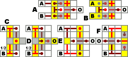
The XOR (⊻) gate
Pronounced "exor". A device which activates when the inputs are not equal to each other.
Adding a NOT gate to the end will produce an XNOR gate, which activates when the inputs are equal to each other.
XOR gate designs. (Click on the image to view the animation)
| A | B | A XOR B |
|---|---|---|
| 1 | 1 | 0 |
| 1 | 0 | 1 |
| 0 | 1 | 1 |
| 0 | 0 | 0 |
| Design | A | B | C | D | E | F | G |
|---|---|---|---|---|---|---|---|
| Size | 3x5x2 | 3x3x3 | 5x5x1 | 3x3x2 | 5x4x2 | 3x3x3 | 5x2x2 |
| Torches | 5 | 5 | 3 | 3 | 3 | 5 | 8 |
| Redstone | 6 | 5 | 14 | 3 | 12 | 4 | 4 |
| Speed (ticks) | 3 | 3 | 2 | 2 | 2 | 3 | 3 |
| Output direction | fwd. | rev. | fwd. | fwd. | fwd. | fwd. | fwd. |
| Requires levers? | No | No | No | Yes | No | No | No |
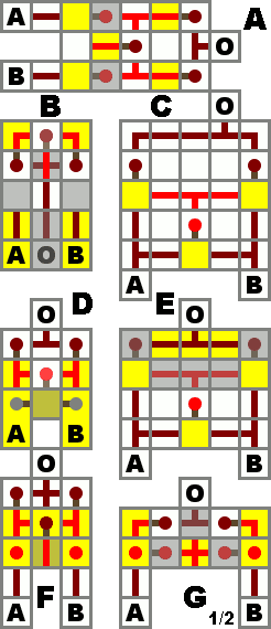
The XNOR gate
XNOR gate designs. (Click on the image to view the animation)
A device which activates when the inputs are equal to each other.
| A | B | A XNOR B |
|---|---|---|
| 1 | 1 | 1 |
| 1 | 0 | 0 |
| 0 | 1 | 0 |
| 0 | 0 | 1 |
| Design | A | B | C | D | E | F |
|---|---|---|---|---|---|---|
| Size | 4x3x2 | 4x3x2 | 2x5x4 | 3x5x3 | 4x5x2 | 4x5x2 |
| Torches | 6 | 4 | 4 | 4 | 4 | 4 |
| Redstone | 5 | 5 | 7 | 7 | 10 | 9 |
| Speed (ticks) | 3 | 2 | 2 | 2 | 2 | 2 |
| Output direction | fwd. | fwd. | fwd. | fwd. | fwd. | rev. |
| Levers required? | No | Yes | No | No | No | No |
The IMPLIES (→) gate
IMPLIES gate.
Represents material implication. Returns false only if the implication A → B is false, that is, if the conditional A is true, but the consequent B is false.
|
|
Latches and Flip-Flops
The common feature in every latch or flip-flop is the RS NOR latch, which amounts to two NOT gates whose inputs and outputs are connected (see below). This allows circuits to store data and deliver it at a later time, rather than acting only on the inputs as given. In other words, functions built from these components can give different outputs in subsequent executions even if the inputs don't change. This allows for the design of counters, long-term clocks, and memory, which cannot be created with logic gates alone.
RS NOR latch

RS NOR latch designs.
A device where Q will stay on forever after input is received by S. Q can be reset by a signal received by R. This is probably the smallest memory device that is possible to make. Note that ~Q means the opposite of Q, e.g. when Q is on, ~Q is off and vice-versa. This means that in certain cases, you can get rid of a NOT gate by simply picking the ~Q output instead of putting a NOT gate after the Q output.
It is useful for making an alarm system were you for example want a warning light to stay turned on after a pressure plate is pressed.
| S | R | Q | ~Q |
|---|---|---|---|
| 1 | 1 | 0 | 0 |
| 1 | 0 | 1 | 0 |
| 0 | 1 | 0 | 1 |
| 0 | 0 | Keep state | Keep state |
| Design | A | B | C | D |
|---|---|---|---|---|
| Size | 3x3x1 | 2x3x2 | 3x3x3 | 4x2x2 |
| Torches | 2 | 2 | 2 | 2 |
| Redstone | 4 | 4 | 8 | 6 |
| Inputs isolated? | Yes | No | Yes | No |
| Outputs isolated? | Yes | Yes | No | No |
| Input orientation | opposite | opposite | adjacent | either |
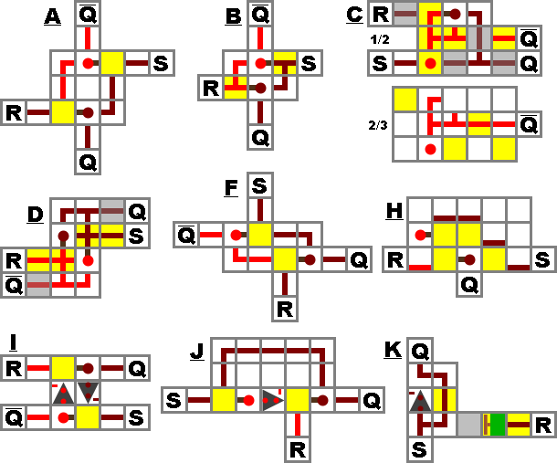
RS NAND latch
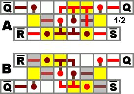
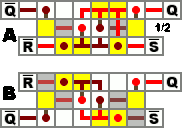
RS NAND latch designs. (Click on the image to view the animation)
When ~S and ~R are both off, Q and ~Q are on. When ~S is on, but ~R is off, Q will be on. When ~R is on, but ~S is off, ~Q will be on. When ~S and ~R are both on, it does not change Q and ~Q. They will be the same as they were before ~S and ~R were both turned on.
Since NOR is the basic logic gate in Minecraft, a design for an RS NAND latch is just an RS NOR with inverters applied to the inputs and outputs.
|
|
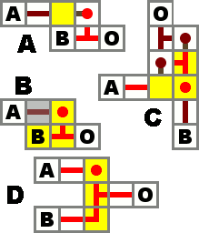
D Flip-Flop
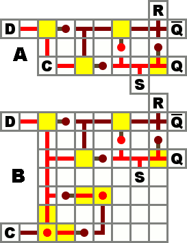
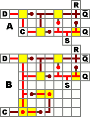
D flip-flop designs.
A D flip-flop, or "data" flip-flop, sets the output to D only on certain conditions. The level-triggering D flip-flop, also known as a D latch, sets the output to D as long as the clock is set to ON. The edge-triggering version will set the output to D only at the moment the clock goes from OFF to ON.
In these designs, the output is not isolated; this allows for asynchronous R and S inputs (which override the clock and force a certain output state).
| Design | A | B |
|---|---|---|
| Size | 7x3x2 | 7x7x2 |
| Torches | 4 | 8 |
| Redstone | 11 | 18 |
| Trigger | Level | Edge |
| Output isolated? | No | No |
JK Flip-Flop
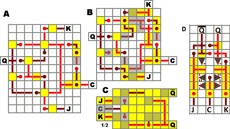

JK flip-flop designs. (Click on the image to view the animation)
An unclocked JK Flip-Flop works a lot like a RS NOR Latch. When the input J is ON and the input K is OFF, the output Q is ON. It will then hold that state until only K or both is ON. When only K is ON the Q is OFF. When both inputs are on they will start a race condition. This means that the output will keep changing until one of the inputs is turned OFF (It doesn't race fast enough to burn out the torches).
NOTE: Some of the illustrated JK Flip-Flops to the right don't include the typical inverse Q output. If you want to use the inverse Q then just add an inverter to the Q.
| Design | A | B | C |
|---|---|---|---|
| Size | 11x9x2 | 9x8x2 | 5x7x4 |
| Torches | 12 | 12 | 11 |
| Redstone | 34 | 35 | 22 |
| Accessible ~Q? | No | No | Yes |
| Trigger | Edge | Edge | Level |
T Flip-Flop
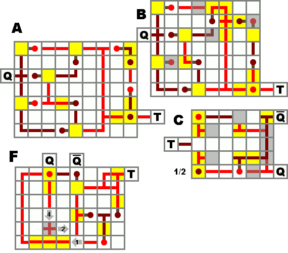
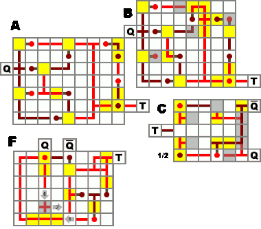
T flip-flop designs. (Click on the image to view the animation)
T Flip-Flops are also known as "toggles". Whenever T changes from 0 (off) to 1 (on), the output will toggle its state.
A useful way to use T Flip-Flops in Minecraft could for example be a button connected to the input. When you press the button the output toggles (a door opens or closes).
It is also the core of all binary counters and clocks, as it functions as a "period doubler", turning two input pulses into one output pulse.
NOTE: Some of the illustrated T Flip-Flops to the right don't include the typical inverse Q outputs. If you want to use the inverse Q then just add an inverter to Q.
| Design | A | B | C |
|---|---|---|---|
| Size | 7x9x2 | 7x8x2 | 5x6x3 |
| Torches | 10 | 10 | 8 |
| Redstone | 28 | 29 | 22 |
| Accessible ~Q? | No | No | Yes |
| Trigger | Edge | Edge | Level |
Clock generators
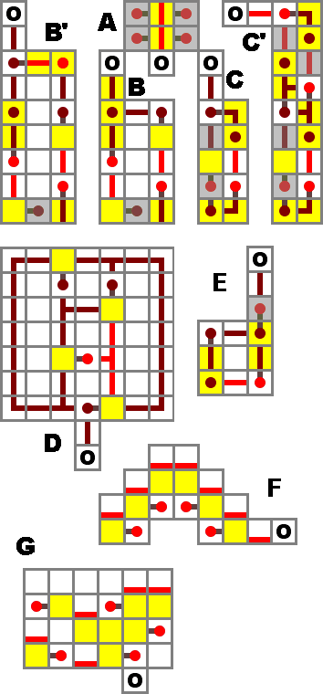
Clock generators and pulsars.
Clock generators are devices where the output is toggling on/off constantly.
The simplest stable clock generator is the 5-clock (designs B and C). Using this method, 1-clocks and 3-clocks are possible to make but they will "burn out" because of their speed, which makes them unstable. Redundancy can be used to maintain a 1-clock, even as the torches burn out; the result is the so-called "Rapid Pulsar" (design A). Slower clocks are made by making the chain of inverters longer (designs B' and C' show how such an extension process can be achieved). It is only possible to make clocks with an odd number of Redstone torches.
Using a different method, a 4-clock can be made (design D). A 4-clock is the fastest clock which will not overload the torches.
The customary name x-clock is derived from half of the period length, which is also usually the pulse width. For example, design D will produce a sequence ...1110000011100000... on the output.
| Design | A | B | B' | C | C' | D |
|---|---|---|---|---|---|---|
| Size | 3x2x2 | 3x5x2 | 3x7x2 | 2x5x2 | 2x9x2 | 7x7x1 |
| Torches | 4 | 5 | 7 (+2) | 5 | 9 (+4) | 4 |
| Redstone | 2 | 5 | 7 (+2) | 4 | 8 (+4) | 28 |
| Pulse width | 1 | 5 | 7 (+2) | 5 | 9 (+4) | 3 |
| Period | 2 | 10 | 14 (+4) | 10 | 18 (+8) | 8 |
Affected Objects
Objects receiving power are affected in the following ways:
- Doors open and close. This is the only method of opening iron doors.
- Tracks
- Tracks will change direction, though always to a turning track.
- TNT will have its charge set. A few seconds of delay should be expected (TNT is not instant).