Latches and flip-flops are effectively 1-bit memory cells. They allow circuits to store data and deliver it at a later time, rather than acting only on the inputs at the time they are given. As a result of this, they can turn an impulse into a constant signal, "turning a button into a lever".
Devices using latches can be built to give different outputs each time a circuit is activated, even if the same inputs are used, and so circuits using them are referred to as "sequential logic". They allow for the design of counters, long-term clocks, and complex memory systems, which cannot be created with combinatorial logic gates alone. Latches are also used when a device needs to behave differently depending on previous inputs.
There are several basic categories of latches, distinguished by how they are controlled. For all types, the input lines are labeled according to their purpose (Set, Reset, Toggle, Data, Clock). There are also more arbitrary labels: The output is commonly labeled for historical reasons. Sometimes there is also an "inverse output" , which is always ON when is OFF and vice versa. If both and are available, we say the circuit has "dual outputs". Most of the following types can be built as a "latch" that responds to the level of a signal, or as a "flip-flop" triggered by a change in the signal.


- A RS latch has separate control lines to set (turn on) or reset (turn off) the latch. Many also have dual outputs. The oldest form of RS latch in Minecraft is the RS-NOR latch, which forms the heart of many other latch and flip-flop designs.
- A T latch has only one input, the toggle. Whenever the toggle is triggered, the latch changes its state from OFF to ON or vice versa.
- There are also SRT latches, combining the inputs and abilities of the RS and T latches.
- A D latch has a data input and a clock input. When the clock is triggered, the data input is copied to the output, then held until the clock is triggered again.
- A JK latch has three inputs: A clock input, and the jump and kill inputs. When the clock is triggered, the latch's output can be set, reset, toggled, or left as is, depending on the combination of J and K. While these are common in real-world electronics, in Minecraft they tend to be bulky and impractical — most players would use an SRT latch instead.
RS latches[]
An RS latch has two inputs, and . The output is conventionally labeled , and there is often an optional "inverse output" . (Having both and is called "dual outputs"). When a signal comes into , is set on and stays on until a similar signal comes into , upon which is reset to "off". indicates the opposite of — when is high, is low, and vice versa. Where a output is available, the player can often save a NOT gate by using it instead of .


Note that the proper name for this category of latch is "SR latch". However, in real-world electronics as in Minecraft, the classic implementation of such latches starts by inverting the inputs; such a latch is the proper "RS latch", but they're so common that the term is commonly used also for what "should" be called SR latches.
Typical uses include an alarm system in which a warning light stays on after a pressure plate is activated until a reset button is pushed, or a rail T-junction being set and reset by different detector rails. RS latches are common parts of other circuits, including other sorts of latches.
Setting both inputs high simultaneously is a "forbidden" condition, generally something to avoid. In the truth table, S=1, R=1 breaks the inverse relationship between and . If this happens, the player will get "undefined behavior" — various designs can do different things, and especially and can be high or low at the same time. If the forbidden state is co-opted to toggle the output, the circuit becomes a JK latch, described in its own section. If there is instead a third input which toggles the output, the circuit becomes an "RST latch".
Any RS latch with dual outputs is functionally symmetrical: pulsing each input turns on "its" output, and turns off the other one. Thus and are interchangeable, if the outputs is swapped: Which input players pick as chooses which of the outputs is , then the other input will be R and the other output will be . (If the original circuit only had a output, then swapping the inputs will turn it into .) In several designs (A, B, C, D, E, F, I) the functional symmetry is reflected by the circuit's physical symmetry, with each input energizing the torch it leads to, while turning off the other.
RS latches can be built in a number of ways:
- Two NOR gates can be linked so that whichever is lit, the other will be off. The RS NOR latch is the "original" RS latch, and still among the smallest memory devices that can be made in vanilla Minecraft. While they can be built with just torches and redstone dust, repeaters can also be used. Many of these designs have "duplex I/O"—the same locations can be used to read or set the latch state.
- It is also possible to construct an RS NAND latch, using NAND gates instead of NOR gates. These will be larger and more complex than an RS NOR latch, but may be useful for specialized purposes. Their inputs are inverted (see below for details).
- Other RS latches can be created by fitting an "input sustaining circuit" with a reset switch, say by adding a pair of NOT gates or a piston, placed so as to interrupt the circuit when triggered. Such a construction can be nearly as compact as an RS NOR latch (and often with better I/O isolation and/or timing), but they will usually not have a natural output.
- Other devices can also be involved. Pistons can be used to physically toggle a block's location, while hoppers or droppers can pass around an item entity. These circuits can be very fast and small, with little redstone dust.
| 1 | 1 | 0 | 0 | Undefined | Undefined |
| 1 | 0 | 0 | 1 | 1 | 0 |
| 0 | 1 | 1 | 0 | 0 | 1 |
| 0 | 0 | 1 | 1 | Keep state | Keep state |


RS-NOR latches[]
Basic RS-NOR Latches
Designs A and B are the most fundamental RS-NOR latches. In both cases, their inputs and outputs are "duplex"—the latch state can be read () or set () on one side of the circuit, while on the other side, the latch can be reset (), or the inverse output read (). If separate lines for input and output are needed, opposite ends of B can be used, or A can be elaborated into A' with separate locations for all four lines.
Isolated RS-NOR Latches
These can be modified to provide separate, even isolated, input and output. C and D use torches and repeaters respectively to isolate the outputs, though the inputs can still be read. E expands the circuit slightly to isolate all four I/O lines.
Vertical RS-NOR Latches
Design F provides a vertical (1-wide) option; again, the I/O is duplex, though isolated outputs can be taken at alternate locations.
Design G takes up more room than F, but may be preferable, as both the set and reset are on the same side. Also, be sure to compensate for the extra tick on (), caused by the last torch.
Design H is smaller than design F in term of height, input and output are on the same height, but it is longer and a bit slower due to the repeater.
Furthermore, it is easily stacked vertically and horizontally (with a shift of 2 blocks on the Y axis).
Design I is similar to design G as it has both set and reset on the same side,but takes up less space. The I/O is duplex, though isolated outputs can be taken at alternate locations.
Design J is similar to design G as it has both set and reset on the same side, but has no slowness due to not having any extra repeaters or torches. This may be more preferable to G, although the outputs (/) are not level with the inputs (R/S).
RS NAND latches[]
An RS latch can also be designed using NAND gates. In Minecraft, these are less efficient than the RS NOR latch, because a single Redstone torch acts as a NOR gate, whereas several torches are required to create a NAND gate. However, they can still be useful for specialized purposes.
Such an "RS NAND latch" is equivalent to an RS NOR, but with inverters applied to all the inputs and outputs. The RS NAND is logically equivalent to the RS NOR, as the same R and S inputs give the same output. However, these designs take inverse R and S (R̅, S̅) as inputs. When S̅ and R̅ are both off, and are on. When S̅ is on, but R̅ is off, will be on. When R̅ is on, but S̅ is off, will be on. When S̅ and R̅ are both on, it does not change and . They will be the same as they were before S̅ and R̅ were both turned on.
RS-NAND Latches
RS-Latch summary table 1[]
This table summarizes the resources and features of the RS latches which use only redstone dust, torches, and repeaters.
| Design | A | B | A' | C | D | E | F | G | H |
|---|---|---|---|---|---|---|---|---|---|
| Size | 4×2×3 | 3×2×3 | 4×4×3 | 2×3×3 | 2×3×2 | 2×4×2 | 3×1×4 | 5×3×3 | 6×3×3 |
| Torches | 2 | 2 | 2 | 2 | 2 | 2 | 2 | 4 | 6 |
| Redstone wire | 6 | 4 | 10 | 4 | 0 | 4 | 3 | 6 | 8 |
| Repeaters | 0 | 0 | 0 | 0 | 2 | 0 | 0 | 0 | 0 |
| Inputs isolated? | Duplex | Duplex | Duplex | Duplex | Yes | Yes | Duplex | Yes | Yes |
| Outputs isolated? | Duplex | Duplex | Duplex | Yes | Yes | Yes | Duplex/Yes | No | Yes |
| Input orientation | opposite | adjacent | opposite | opposite | opposite | opposite | opposite | perpendicular | perpendicular |
Analog RS latch[]
This latch will maintain the highest signal level that arrived from input S if R is off, and fade (reduce memorized signal strength) by strength of R every two redstone ticks. For maximum strength (15) signals it behaves like any other RS latch, but it can also memorize intermediate signal levels, and since 2-tick pulses on R will subtract their strength from its memorized state, it makes a nice element of counter or countdown circuits.
Analog counter[1][]
This variant of the analog RS latch adds an "increment" (I) and "decrement" (D) input. While input I is active, memorized signal strength is increased by 1 every two redstone ticks until reaching maximum (15) signal strength. While input D is active, signal strength is decreased by 1 every two redstone ticks until output Q is unpowered.
Output Q is duplex and can also be used as an input (S); the highest signal strength at this block will be memorized.
Input stabilization with reset[]
An "Input-Stabilizing Circuit" responds to an input pulse by turning its input on and leaving it on. This can be built up into an RS Latch by adding a means to turn it off. These circuits usually don't offer a "natural" output. Design J adds a pair of NOT gates, with the reset going to the second torch. (The NOT gates can also be added to the upper redstone loop.) Design K uses its piston to block the circuit where it goes up onto the solid block. Design L shows the reverse approach, breaking the circuit by withdrawing a power-carrying block.
RS-ISR Latches
Pistons and other devices[]
Other RS Latches
A pair of non-sticky pistons can be used to physically push a block back and forth. This can make or break a circuit from a torch, producing an RS latch with no inverse output (M). If the block being pushed is a block of redstone, the circuit can be even smaller, with dual outputs (N). Both of these have isolated inputs and outputs. Putting two blocks between the pistons produces an SRT latch O, with an extra input to toggle the latch state. And droppers can also be pressed into service, as in design P: Small, tileable, but it does require a comparator.
Variations[]
- Expand an RS latch easily into a monostable circuit, which automatically disables itself some time after activation. To do this, split the output redstone path into two parts. The new path should run through some repeaters, and in to the reset input. When players turn on the latch, redstone feeds a signal through the delay before turning off the latch. This works not only for and R, but for and S as well. A more complex delay mechanism, such as a water clock, can replace the repeaters.
- An "Enable/Disable RS latch" can be made by adding a pair of AND gates in front of the inputs, testing each of them against a third input, E. Now if E is true, the memory cell works as normal. If E is false, the memory cell will not change state. That is, E latches (or equivalently, clocks) the RS latch itself. Note that for design Q, the outputs are not isolated, and a signal to them can set the latch regardless of E. Alternatively, repeaters could be used to latch the inputs, but this costs more and saves no space.
- As noted above, if it is possible to add a "toggle" input, the RS latch becomes an RST latch. If the "forbidden" state is used for the toggle, then it's a JK latch.
Dropper SR latch[]
Allows a lot of flexibility in geometry — the droppers can be read from 3 sides each and activated from 5 sides each; can be oriented vertically too and content can be read with comparators through solid blocks. However, always power it through an adjacent block; if players power the dropper directly, they will activate the other dropper too and the order is unpredictable. Activates on rising edge, meaning they can apply S even while R is still active or vice versa.
Enable/Disable RS Latch
RS latch summary table 2[]
| Design | J | K | L | M | N | O | P | Q |
|---|---|---|---|---|---|---|---|---|
| Size | 2×3×3 | 4×3×3 | 4×4×2 | 4×3×2 | 4×1×1 | 5×3×3 | 3×1×2 | 5×5×3 |
| Torches | 2 | 0 | 1 | 1 | 0 | 1 | 0 | 7 |
| Dust | 7 | 4 | 6 | 0 | 9 | 4 | 0 | 7 |
| Repeaters | 1 | 1 | 1 | 1 | 0 | 1 | 0 | 0 |
| Other devices | -- | 1 sticky piston | 1 sticky piston | 2 normal pistons | 2 normal pistons | 2 normal pistons | 2 droppers, 2 comparators | N/A |
| Inputs isolated? | Yes, | No | No | Yes | Yes | No | Yes | Yes |
| Outputs isolated? | Yes | No | No | Yes | Yes | Yes | Yes | No |
| available? | No | No | No | No | Yes | No | Yes | Yes |
| Input orientation | Perpendicular | Perpendicular | Adjacent | Opposite | Opposite | Opposite | Adjacent | Adjacent |
D latches and flip-flops[]
A D ("data") flip-flop or latch has two inputs: The data line D, and the "clock" input C. When triggered by C, the circuits set their output () to D, then hold that output state between triggers. The latch form, a "gated D latch", is level triggered. It can be high- or low-triggered; either way, while the clock is in the trigger state, the output will change to match D. When the clock is in the other state, the latch will hold its current state until triggered again. A D flip-flop is edge triggered; it sets the output to D only when its clock input changes from "off" to "on" (rising edge) or vice versa (falling edge), according to the circuit. An edge trigger can turn a gated D latch into a D flip-flop.
Building these devices with torches is fairly unwieldy, though some older designs are given below. Repeaters have a special latching ability, which drastically simplifies the problem. Now a gated D latch can be made with two repeaters, and a D flip-flop with four repeaters and a torch:
Design G uses the repeater's latching feature, which is added to the game in Java Edition 1.4.2. It holds its state while the clock is high, and is by far the most compact of the D latch designs. Design H combines two such latches, one high and one low triggered, to create a rising edge-triggered D flip-flop. The block and redstone torch can be reversed for a falling edge-triggered design. The design is based on a real life implementation of an edge-triggered D flip-flop called a "Master-Slave" configuration.
Analog D latch[]
- 6×4×2 (48 block volume)
- flat, silent
- circuit delay: 3 ticks
- Earliest Known Publication: May 26, 2018[2]
Design J is an analog version of a low-triggered D latch. The signal strength of the output is the same as input D when the latch is triggered.
For maximum strength (15) signals for D, this latch behaves like a normal (digital) low-triggered D latch.
Torch-based designs[]
For historical interest, here are several older designs, not dependent on latched repeaters, along with a table of their resource needs and other characteristics. A few of these designs also have the additional inputs and inverse output of an RS latch.
This basic level-triggered gated D latch (design A) sets the output to D as long as the clock is set to OFF, and ignores changes in D as long as the clock is ON. However, on a rising clock edge, if D is low, the output will pulse high for 1 tick, before latching low.
Design B includes a rising-edge trigger and it will set the output to D only when the clock goes from OFF to ON. The torch-based edge trigger could also be replaced with one of the designs from the Pulse circuit page.
These are RS latch-based circuits with appropriately set front-ends. Directly trigger the RS latch using the R and S inputs to override the clock, forcing a certain output state. Sending signals into the and lines works similarly, because the output is not isolated. To isolate the outputs, add inverters and swap the labels.
D Latch A
D Latch B
Design C is a one block wide vertical version of A, except for using a non-inverted clock. It sets the output to D while the clock is ON (turning the torch off). This design can be repeated in parallel every other block, giving it a much smaller footprint, equal to the minimum spacing of parallel data lines. A clock signal can be distributed to all of them with a wire running perpendicularly under the data lines, allowing multiple flip-flops to share a single edge-trigger if desired. The output is most easily accessed in the reverse direction, toward the source of input. As in design A, the un-isolated and wires can do double duty as R and S inputs. can be inverted or repeated to isolate the latch's Set line.
D Latch C
D Latch D
Design E provides a more compact (but more complex) version of A, while still affording the same ceiling requirement. E' allows the latch to act on a high input.
Design F holds its state while the clock is high, and switches to D when the clock falls low. The repeater serves to synchronize the signals that switch out the loop and switch in D. It must be set to 1 to match the effect of the torch.
D Latch E
D Latch F
| Design | A | B | C | D | E | E' | F | G | H |
|---|---|---|---|---|---|---|---|---|---|
| Size | 7×3×3 | 7×7×3 | 6×1×5 | 5×2×6 | 5×3×3 | 5×3×3 | 5×3×3 | 2×1×2 | 3×2×2 |
| Torches | 4 | 8 | 5 | 6 | 4 | 5 | 4 | 0 | 1 |
| Redstone wire | 11 | 18 | 5 | 6 | 10 | 9 | 7 | 0 | 0 |
| Repeaters | 0 | 0 | 0 | 0 | 0 | 0 | 1 | 2 | 4 |
| Trigger | Low Level | Rising Edge | High Level | High Level | Low Level | High Level | Low Level | High Level | Rising Edge |
| Output isolated? | No | No | No | No | No | No | Yes | Yes | Yes |
| Input isolated? | Yes | Yes | C Only | C Only | Yes | Yes | No | Yes | Yes |
BUD-based D flip-flop[]
Piston BUD based D Flip-flop
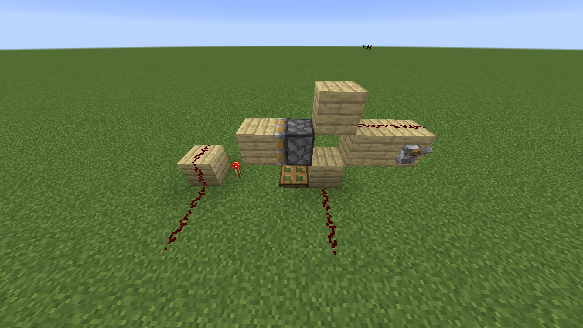
Design I represents an entirely different form of the D flip-flop, based on the principle of the block update detector. This flip-flop is small so it can be used multiple times at large integrated redstone circuits. Note that no blocks that are adjacent to the piston can be used as circuit components except flip-flop itself.
The lever in the screenshot shown is the D input. The redstone wire in the middle is trigger signal input. The trapdoor is part of the BUD – it need be replaced by a note block, an activator rail, etc.
JK flip-flops and latches[]
A JK flip-flop is another memory element which, like the D flip-flop, will only change its output state when triggered by a clock signal C. They can be edge-triggered (designs A, D, E) or level-triggered (C). Either way, the two inputs are called J and K. These names are arbitrary, and somewhat interchangeable: if a output is available, swapping J and K will also swap and .
| J | K | Qnext |
|---|---|---|
| 0 | 0 | |
| 0 | 1 | 0 |
| 1 | 0 | 1 |
| 1 | 1 |
When the flip-flop is triggered the effect on the output will depend on the values of the two inputs:
- If the input J = 1 and the input K = 0, the output Q = 1.
- When J = 0 and K = 1, the output Q = 0.
- If both J and K are 0, then the JK flip-flop maintains its previous state.
- If both are 1, the output will complement itself — i.e., if before the clock trigger, afterwards.


The table summarizes these states — note that is the new state after the trigger, while represents the state before the trigger.


The JK flip-flop's complement function (when J and K are 1) is only meaningful with edge-triggered JK flip-flops, as it is an instantaneous trigger condition. With level-triggered flip-flops (e.g. design C), maintaining the clock signal at 1 for too long causes a race condition on the output. Although this race condition is not fast enough to cause the torches to burn out, it makes the complement function unreliable for level-triggered flip-flops.
The JK flip-flip is a "universal flip-flop", as it can be converted to any of the other types: It's already an RS latch, with the "forbidden" input used for toggling. To make it a T flip flop, set J = K = T, and to make it a D flip-flop, set K to the inverse of J, that is J = K̅ = D. In the real world, mass production makes JK latches useful and common: a single circuit to produce in bulk, that can be used as any other sort of latch. In Minecraft, however, JK latches are generally larger and more complex than the other types, and using their toggle function is awkward. It's almost always easier to build the specific latch type needed. Notably, an SRT Latch has all the same abilities, but gets the toggle function from a separate input.
Design E is a vertical JK Flip-Flop from the basis of design A.
Aside from these redstone designs, it is also possible to make a JK flip-flop by modifying a rail toggle, or with newer components such as hoppers and droppers.
JK Latch A
JK Latch C
JK Latch D
JK Latch E
Design table[]
| Design | A | C | D | E |
|---|---|---|---|---|
| Size | 9×2×11 | 7×4×5 | 5×2×7 | 14×10×1 |
| Torches | 12 | 11 | 8 | 10 |
| Redstone | 30 | 23 | 16 | 24 |
| Repeaters | 0 | 0 | 6 | 6 |
| Accessible ? | No | Yes | Yes | No |
| Trigger | Edge | Level | Edge | Edge |
T flip-flop[]
T flip-flops are also known as "toggles". Whenever T changes from OFF to ON, the output will toggle its state. A useful way to use T flip-flops in Minecraft could, for example, be a button connected to the input. When players press the button the output toggles (a door opens or closes), and does not toggle back when the button pops out. These are also the core of all binary counters and clocks, as they function as a "period doubler", releasing one pulse for every two received.
There are many ways to build a T flip-flop, ranging from torches and dust through pistons to more exotic devices. Many designs depend on a quirk in sticky-piston behavior, namely that after pushing a block, a sticky piston will let go of it if the activating pulse was 1 tick or less. This allows short pulses to toggle the position of a block, which is very useful here.
Best in class TFF designs[]
These are designs which seem markedly superior in various categories.
T Latch L3
T Flip-flop L4
T Flip-flop L5
T Flip-flop L6
T Flip-flop L7
L3 is a latch, which responds to a high level. Like most T latches, if the toggle line is held high too long, it will "oscillate", toggling repeatedly. A stone button will produce a single pulse, while wooden button's pulse is long enough to cause oscillation.
L5 is a true flip-flop with the same footprint as the L3(but higher), which triggers on a rising edge. Both are extremely compact, thanks to the use of latched repeaters.
L6 is a compact 1-high adaptation of D flip-flop H. The video shows L6 and a similar T flip-flop.
L4 and L7 are basically two opposite halves of the same machine — both are extremely compact and customizable tick-wise but L4 is made for off-pulses with durations ranging from 2 to 8 redstone ticks while L7 is made for on-pulses with durations that are 9+ redstone ticks long which includes the 10-tick stone button. Customizing each requires changing the repeater delay or adding repeaters to match the trigger duration.
To customize L4 for your use, adjust the top most repeater according to the duration of your trigger, as shown in the table below:
| Off-pulse Duration (Redstone Ticks) | Recommended Setting for Output Repeater |
|---|---|
| 1 | N/A - Use a Sticky Piston |
| 2 | 1 |
| 3 | 2 |
| 4 | 2 |
| 5 | 3 |
| 6 | 3 |
| 7 | 4 |
| 8 | 4 |
| 9+ | N/A
- Use TFF O or L7 |
| L6 and another TFF (view on YouTube) |
|---|
Piston TFF designs[]
This design doesn't use the quasi-connectivity effect, so it works in both Bedrock and Java editions. It uses a pulse generator that feeds into repeaters that power the piston through a solid block and an underground redstone dust patch. The redstone block position is the output value of the TFF. This design requires one sticky piston (for the repeater) and two non-sticky pistons, and a 6×6 area, which is linear-tilable so that the output of one TFF feeds into the next TFF.
Bedrock Edition Piston TFF
The following designs work in Java Edition but may present difficulties in Bedrock Edition.
Linear tilable TFF M
3×3 piston TFF N
2 piston QC TFF O
TFF R
Design M is a 1-wide dual-piston design, which can be tiled adjacent to each other for compact circuitry. (If they don't have to be right next to each other, dust can be used instead of the input and output repeaters.) The hidden piston forms a simple monostable circuit that cuts off the button signal (10 ticks or so) as soon as a 1-tick signal has passed through to the second repeater. Due to the piston quirk mentioned above, this 1-tick signal lets the main piston toggle the position of its mobile block, to set or unset the latch and the output. It can be made more compact by removing the last block, the repeater and the torch and replacing the block in front of the last piston with a redstone block.
That linear design can also be bent into a 3×3 square, as N. (The "any" blocks can be air, and that torch can just as well be on the ground.) Tiling design N is a little tricker, but it can be done in either horizontal direction, by mirroring adjacent copies. Note that the output can be taken from whichever side of that corner is free, but the player will need repeaters to keep adjacent outputs from cross-connecting.
Design O, based on the quasi-connectivity effect that works only in Java Edition, uses a redstone block that swaps positions when the top dust receives a signal; it is a dual piston design that uses only two pistons, two torches, two dust, and two solid blocks and a redstone block. While one of the most compact designs; using only 10 blocks of space before inputs and outputs in addition to being 1 wide and vertical, it also requires no slime balls and uses few resources aside from the redstone block while allowing for four areas to input and 4 areas to output (if repeaters are used for the output, 2 if not), in addition it can be built in the air since it doesn't have any redstone or repeaters that require placement on the ground. The design toggles on a falling edge.
Design R is a variation of design O, and it adds the ability to reset the output to 0, using the input R.
Observer TFF designs (Java Edition)[]
T Flip-flop O1
T Flip-flop O2
T Flip-flop O3
Those designs make use of observers and the quasi-connectivity effect. Designs O1 and O2 work for a rising signal, while the O3 toggles on a falling signal.
Design table[]
| Design | O1 horizontal | O1 vertical | O2 | O3 |
|---|---|---|---|---|
| Size | 6x1x1 | 3×4×1 | 5×2×1 | 4x2x1 |
| Observers | 1 | |||
| Redstone blocks | 1 | |||
| Sticky pistons | 2 | |||
| Trigger | rising | falling | ||
| Delay | 2 | |||
Other conventional TFF designs[]
T Flip-flop A
T Flip-flop B
T Latch D
T Flip-flop E
T Flip-flop J
T Flip-flop K
T Flip-flop P
Design A demonstrates that a TFF can be made solely with redstone dust and torches, but it sprawls over 9×7×3 blocks. Design B is slightly unreliable for very long pulses; while the input is on, the piston will toggle every time the block below the piston arm is updated.
Design D (another torches-and-dust design, but vertical) does not have an incorporated edge trigger and will toggle multiple times unless the input is passed through one first. Design E adds such a trigger (and a repeater).
Designs J and K make more use of repeaters, but not as latches, and they are still quite large.
T Flip-flop L1
T Flip-flop L2
Design L2, (also L3, L4, and L5 above) relies on the redstone repeater locking mechanic introduced in Java Edition 1.4.2. L4 is the smallest, but requires a piston and activates on a falling edge.
T Flip-flop Z3
T Flip-flop Z4
T Flip-flop Z5
TFF summary table[]
| Design | A | B | D | E | J | K | M | P | R | |
|---|---|---|---|---|---|---|---|---|---|---|
| Size | 7×9×3 | 5×6×3 | 1×7×6 | 1×11×7 | 3×7×3 | 3×7×3 | 1×7×3 | 3×4×4 | 5x5x2 | 4×5×4 |
| Redstone wire | 28 | 14 | 9 | 13 | 11 | 9 | 0 | 2 | 8 | 8 |
| Torches | 10 | 4 | 7 | 12 | 5 | 5 | 1 | 3 | 7 | 4 |
| Repeaters | 0 | 0 | 0 | 1 | 3 | 2 | 3 | 0 | 0 | 1 |
| Other Devices | none | 1 SP | none | none | none | none | 2 SP | 2 P | none | 3 SP |
| Input isolated? | Yes | Yes | Yes | Yes | Yes | Yes | Yes | No | Yes | No |
| Output(s) isolated? | No | No | No | No | only | No | Yes | No | No | No |
| available? | No | No | No | No | Yes | No | No | No | Yes | No |
| Trigger | rising | rising | rising | rising | rising | rising | rising | falling | rising | falling for both T and R |
| Delay | 4 | 3 | 4 | 3 | 1 | 3 for R, 1 for T | ||||
| Cycle time | ||||||||||
| Other | BUD | tilable |
| Design | L1 | L2 | L3 | L4 | L5 | L6 |
|---|---|---|---|---|---|---|
| Size | 3×6×3 | 3×5×2 | 3×4×2 | 2×3×1 | 3×4×3 | 4×4×2 |
| Redstone wire | 4 | 6 | 2 | 2 | 4 | 4 |
| Torches | 4 | 2 | 2 | 0 | 2 | 2 |
| Repeaters | 4 | 3 | 3 | 3 | 4 | 4 |
| Other devices | 1 SP | none | none | none | none | none |
| Input isolated? | Yes | Yes | Yes | No | Yes | Yes |
| Output(s) isolated? | Yes | Yes | Yes | Yes | only | No |
| available? | Yes | No | No | No | Yes | Yes |
| Trigger | rising | rising | high | falling | rising | rising |
| Delay | 3 | 5 | 1/2 Trigger Duration | 4 () | 4 | |
| Cycle time | Trigger Duration | 6 |
| Design | Z3 | Z4 | Z5 | ||
|---|---|---|---|---|---|
| Size | 3×3×3 | 3×5×3 | 1×6×5 | 3×5×3 | 1×5×4 |
| Redstone wire | 4 | 4 | 4 | 4 | 2 |
| Torches | 2 | 3 | 3 | 3 | 2 |
| Repeaters | 1 | 2 | 2 | 2 | 2 |
| Other devices | 1 SP | 1 SP | 1 SP | 1 SP | 1 SP |
| Input isolated? | Yes | Yes | Yes | Yes | Yes |
| Output(s) isolated? | Yes | Yes | Yes | Yes | Yes |
| available? | No | No | No | No | No |
| Trigger | |||||
| Delay | |||||
| Cycle time |
- Size
- "In a void", that includes required blocks supporting redstone.
- Delay
- The number of ticks from the trigger to switching the output.
- Cycle time
- How often the latch can toggle, including any recovery time. This is the period of the fastest clock that can drive it.
- Other Devices
- P == normal piston, SP == sticky piston, C == comparator, H == hopper, D == dropper.
- Trigger
- rising edge (the usual), falling edge, high or low level. Level-triggered TFFs oscillate on long pulses.
Rail and exotic TFFs[]
Pressure-Plate Rail TFF (B)
Basic Rail TFF (A)
The rail T flip-flop is a T flip-flop which uses rails and redstone. The general design uses a length of track that is stopped by a block at both ends. When the T flip-flop is in a stable state, the minecart is at either end of the track (depending on the state). An input pulse turns on powered rails at both ends of the track, causing the minecart to move to the other end.
Along the track, there are two separate detector elements (e.g. detector rails). These two detectors are each connected to an input of an RS NOR latch, and hence serve to translate minecart motion into a state transition. When the minecart moves, depending on its direction of motion, one detector will turn on (and off) before the other; the second detector to be hit is what determines which input of the RS NOR latch stays on last and hence what the new state of the RS NOR latch is.
Design A uses detector rails, while design B uses pressure plates. (A minecart triggers a pressure plate on the inside of a turn, including diagonals.) Note that for B, the other side of the latch isn't a true , as the passage of the cart turns on before actually switching the latch.
This type of T flip-flop is slower than traditional redstone-only circuits, but this may be desirable in certain situations. With T flip-flop designs that are level-triggered (as opposed to clocked or edge-triggered), a long input pulse will cause the flip-flop to continuously switch state (oscillate) while the pulse is present. In pure redstone circuits, this is only limited by the redstone circuit delays, and hence a relatively short input pulse can cause several state transitions. Pure redstone T flip-flops usually include an edge-trigger or pulse-limiting circuit to the design, since the input pulse usually can't be guaranteed to be short enough without the use of that kind of circuit.
With rail-based designs, the speed at which the output can flip is limited by the time needed for the cart to move from one end of its rail to the other, which allows for a much longer pulse to be applied to a level-triggered input without needing an edge-trigger or pulse limiter circuit. However, the delay between the input pulse and the output transition is also longer.
Grizdale's T flip-flop[]
Grizdale's Compact TFF
This hopper/dropper design is not only compact, but tileable in three dimensions. The only hitch (for survival mode) is that the player needs access to nether quartz for the comparator.
The A variant has a size of 1×2×3. The B variant puts the input and output inline, but changes the footprint to 2×2×2, or 4×2×2 if players want fully powered input and output. The B design can also be tiled in line, side by side, vertically (by reversing alternate rows), or all three at once.
Once built, place a single item inside any of the containers and it will work as a T flip-flop, with the item cycling between the two droppers. The core has a 1 tick delay between input and turning off or on, but the optional repeaters would raise this to 3.
This T Flip Flop can be turned into an SRT latch by only powering the bottom dropper to set, and the top to reset. However, it won't be as tileable as the original TFF.
Obsolete T flip-flops[]
T Flip-flop Z1
T Flip-flop Z2
Designs Z1 and Z2 do not work as of Java Edition 1.5.2 — in both cases, their pulse generator does not cause the piston to toggle its block as apparently intended.
References[]
- ↑ JavaChef (March 24, 2024) "Minecraft: Analog Counter / Memory Latch "
- ↑ R.K.F. Walter (May 26, 2018) "Tutorial: Simple, Analogue Gated Memory & Long Delay Circuits"