{{schematic}} if possible.Logic gates in Minecraft are a way of using redstone circuits in a manner that a certain combination of inputs, or redstone signals, achieves a certain output. They are similar to computer logic gates in a way, but are slightly different in their constructs.
Basic Info
Some basic info about Minecraft needed to understand redstone circuits and gates:
- There are several items that can provide an input charge into redstone. These are levers, pressure plates, redstone torches, redstone blocks, buttons, detector rails, tripwire hooks and daylight sensors.
- Switches are most commonly used with gates because of their ease of use and the fact that they are easily made.
- When redstone torches are powered, they go into an "off" state and stop providing power themselves.
- Any block can have redstone placed on it except leaves and glass, with a few more exceptions.
- Glowstone can have redstone wire placed on it, but not torches or repeaters.
- Redstone wire can no longer be placed on Glowstone in the Console Edition as of Version 1.3 (TU7).
Key for Diagrams
Using Logic Gates
The most basic gate you can have. When the input signal is on, the output signal is on, and vice versa.
One uses gates when they need a different signal pattern than a simple on/off pattern, but a gate can be as simple as that: an On-On, Off-Off gate. However, other gates are used when one wants to have a signal go on when a certain combination of events happens. For instance, if you wanted to have a redstone lamp light only when two switches were both toggled to the "on" position, you would use an AND gate. If you wanted no signal when a switch is on, but wanted a signal when a switch is off, you would use a NOT gate. Lighting in modern buildings controlled by two or more switches (for example: a light in a hallway with a switch at each end) use XOR gates.
Gates can be used in combinations to create complex signal patterns, and some have even successfully created redstone computers using logic gates. See Tutorials/Advanced redstone circuits for more info.
Examples of Logic Gates
NOT Gate
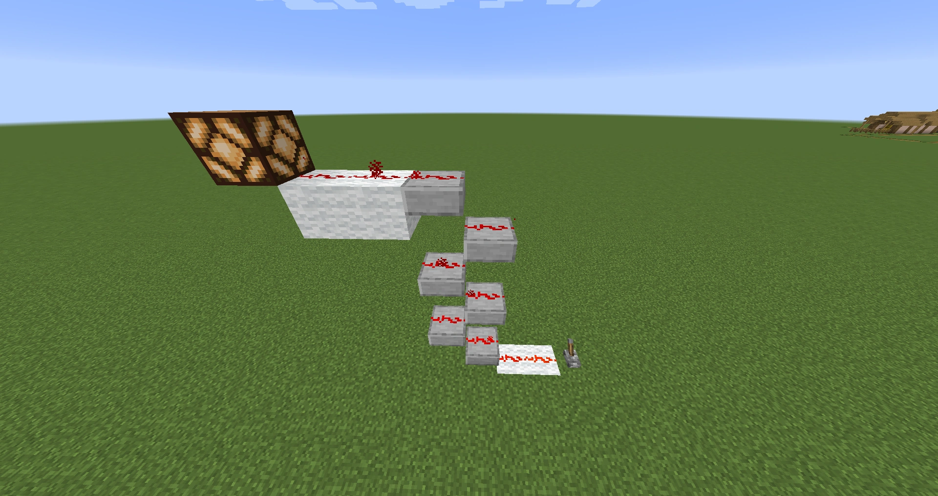
The most commonly used NOT gate. Also called an inverter.
Interactive Schematic
A NOT gate (¬A), also known as an inverter, is a gate used when you want an opposite output from the input you give. For instance, when the switch, or input, is set to "on", the output will be toggled to "off", and when the switch is toggled to "off", the output will be toggled to "on".
| Input | Output |
|---|---|
| ON | off |
| off | ON |
AND Gate
A commonly-used AND gate.
Interactive Schematic
An AND gate (A^B) is used with two or more switches or other inputs. The output is toggled to "on" ONLY when both switches, or inputs, are toggled to "on". Otherwise, the output will remain "off".
| Input 1 | Input 2 | Output |
|---|---|---|
| ON | ON | ON |
| ON | off | off |
| off | ON | off |
| off | off | off |
NAND Gate
A commonly used NAND gate. Note the similarities to the AND gate.
Interactive Schematic
A NAND gate -(A^B) is the opposite to the AND gate. The output is toggled to "off" ONLY when both switches are toggled to "on". Otherwise, the output is set to "on". This gate also requires two or more inputs.
| Input 1 | Input 2 | Output |
|---|---|---|
| ON | ON | off |
| ON | off | ON |
| off | ON | ON |
| off | off | ON |
OR Gate
An OR gate (AVB) uses two or more inputs. Whenever any input is "on", the output is to "on". The only time the output is "off" is when all inputs are "off".
| Input 1 | Input 2 | Output |
|---|---|---|
| ON | ON | ON |
| ON | off | ON |
| off | ON | ON |
| off | off | off |
NOR Gate
A NOR gate. Note the similarities to the OR gate.
Interactive Schematic
A NOR gate -(AVB) is the opposite of the OR gate. Whenever at least one switch is toggled to "on", the output is toggled to "off". The only time the output is "on" is when all inputs are toggled to "off". This gate also uses two or more inputs.
| Input 1 | Input 2 | Output |
|---|---|---|
| ON | ON | off |
| ON | off | off |
| off | ON | off |
| off | off | ON |
XOR Gate
| Input 1 | Input 2 | Output |
|---|---|---|
| ON | ON | off |
| ON | off | ON |
| off | ON | ON |
| off | off | off |
An XOR gate (A⊕B) is a gate that uses two inputs. In this gate, the output is toggled to "on" when one switch is "on" and one switch is "off". If both switches are in the same position, the output is toggled to "off". Because of these properties, XOR gates are commonly found in complex redstone circuits. In some cases, it is possible to get an OR gate output and an AND gate output on different channels.
- XORgate.png
A commonly-used XOR gate. Interactive Schematic

A Comparator XOR Gate.
- XOR Gate Version 2.png
A Comparator XOR gate with side-by-side inputs.
| Example of XOR Gate (view on YouTube) |
|---|
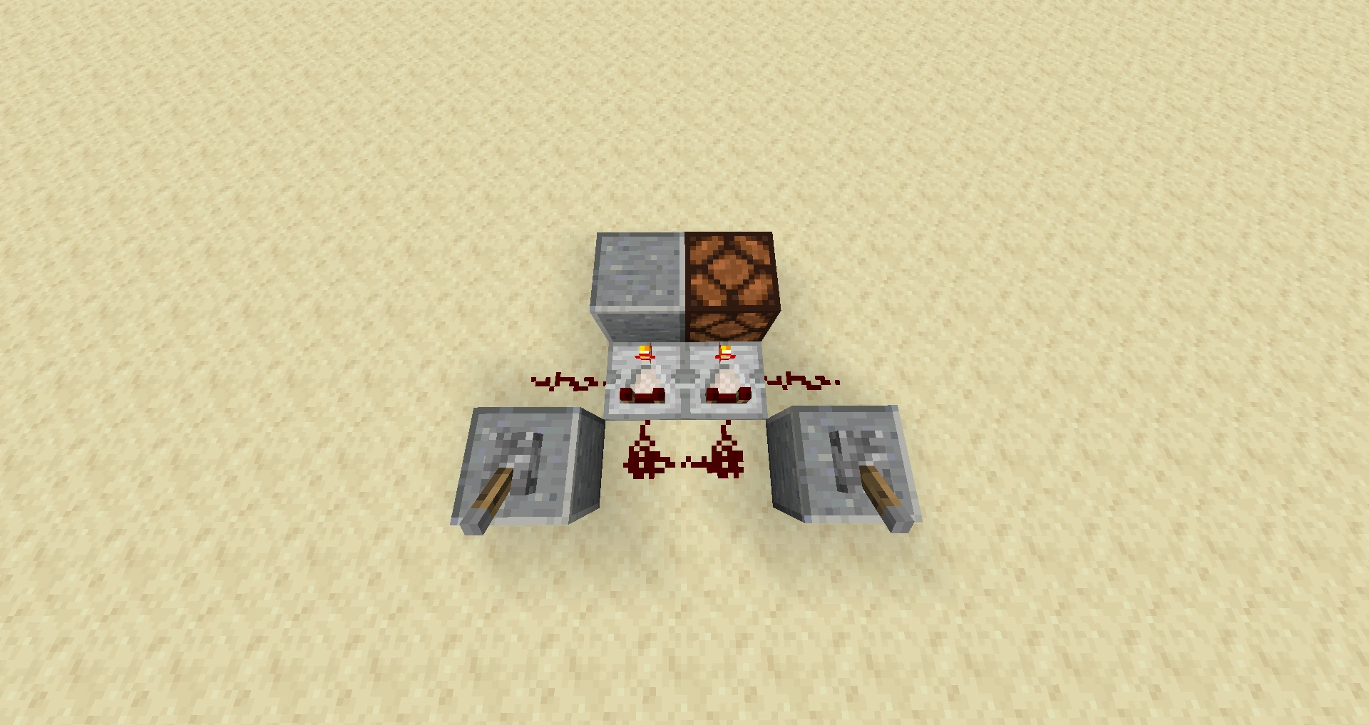
XNOR Gate
A commonly-used XNOR gate. Note the similarities to the XOR gate.
Interactive Schematic
An XNOR gate (A⇔B) is the opposite of an XOR gate. It uses two inputs. When both switches are in the same state (both switches are "on" or both switches are "off"), then the output is toggled to "on". Otherwise, if the switches differ, the output is toggled to "off".
| Input 1 | Input 2 | Output |
|---|---|---|
| ON | ON | ON |
| ON | off | off |
| off | ON | off |
| off | off | ON |
ONLY Gate
In this gate, the output is toggled to "on" only when input A is "on" and input B is "off". If input A is "off and input B is "on", the output will remain "off". If both inputs are "off" or "on", the output will remain "off". This makes this gate useful when needing a specific order of inputs to trigger the output.
(Sorry I do not know how to add Pictures, here is the link to the Schematic) http://mordritch.com/mc_rss/5244
Diodes
Diodes prevent power from flowing backwards in a circuit. This can be very useful if you need to isolate an input wire to avoid feedback, or need to merge two inputs into one (such as in the OR gate above).
There are three flavors of diodes: The one-block one (up to four) tick delay repeater, the three-block two tick delay redstone torch repeater(also called a classic or traditional repeater), and the two-block, zero tick delay Glowstone diode.

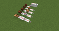
Two repeaters used in a compact wire crossing.
Interactive Schematic
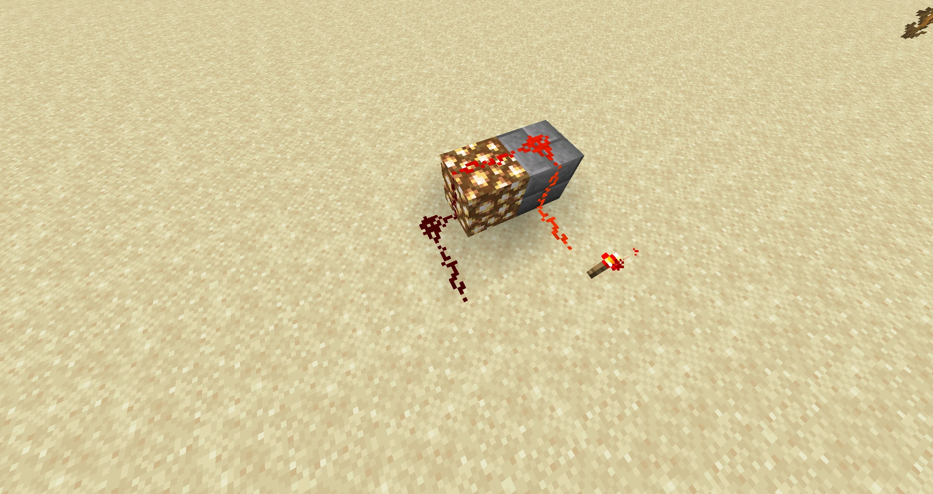
Repeater
Repeater based diodes are the easiest to make, by simply placing a repeater in a line of redstone, you have a simple one-tick delay diode. This simple mechanism can be seen demonstrated in the image to the right.
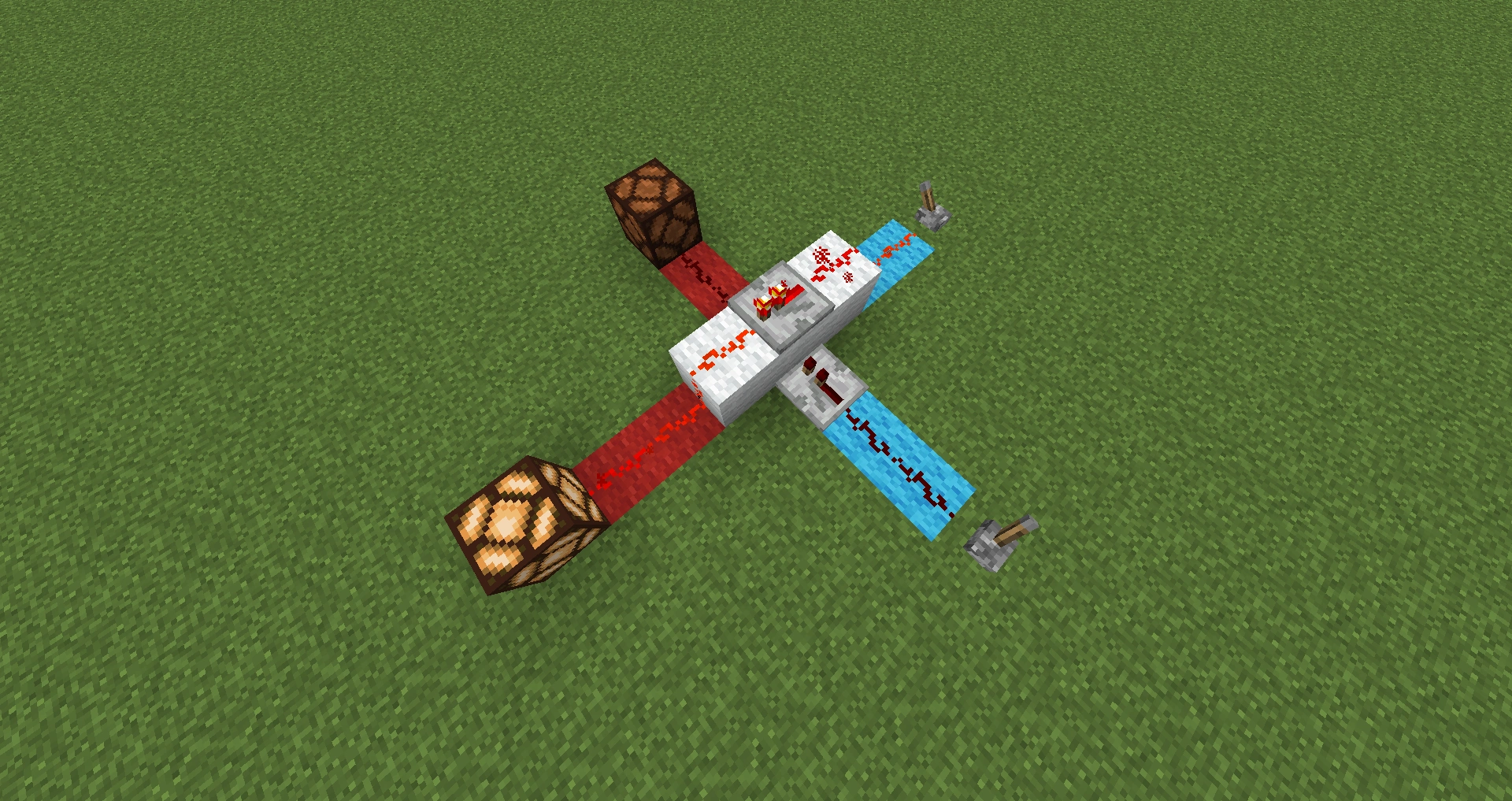
Torch Repeater
A basic traditional repeater design.
Interactive Schematic
Torch based repeaters are effective for making diodes (at a heavy cost of two ticks, however) because torches do not go out if you power them from a block they are not attached to. They are simply two NOT gates (and can be spaced much wider, allowing more transmission range at a lower cost than repeaters), by placing two solid blocks (not glass, glowstone, leaves, etc.) then a torch on the top of the block you're sending power to you create the first NOT gate, you then lay wire on the second block and place a torch on one side, this second torch will be switched off (after a brief pulse, careful!) by the torch on the first block. If you like, you can also lay wire instead of placing the torch immediately, up to 15 blocks of it; after 15 blocks, however, you must place a third block at the very end and place the second torch on one side of that before you continue laying wire.
A possible alternative to placing two blocks for the first torch if you're doing long distance transmission is to dig one block down, and place wire in the hole then place a torch on the block the wire in the hole connects to. This will give you the final block for the other NOT gate as well, so you don't need to carry spare blocks for your repeaters/diodes.
Glowstone, Stairs, and Slabs
Glowstone, Stairs, and Slabs are utilities in redstone circuits due to a few interesting features of how they transmit power. They all:
- allow power to go through their lower and upper edges (see vertical transmission below)
- allow power to transmit up to a wire on its surface (top).
- do not allow power to transmit from its surface to a block below.
That last feature is the most used. Among other things, it allows the use of these to construct a diode. Placing redstone up to one of these blocks, across to a normal block on the same level then back down (see figure) creates a zero-tick-delay diode that prevents feedback loops in time-sensitive circuits.
That same feature also allows for 1-wide, 2-deep instant vertical redstone transmission.

A diode made using glowstone.
Examples in different scenarios

Instant vertical transmission of redstone using slabs

Video
Tutorials/Basic logic gates/video