This tutorial will show you how to make a calculator in Minecraft using redstone.
Resume[]
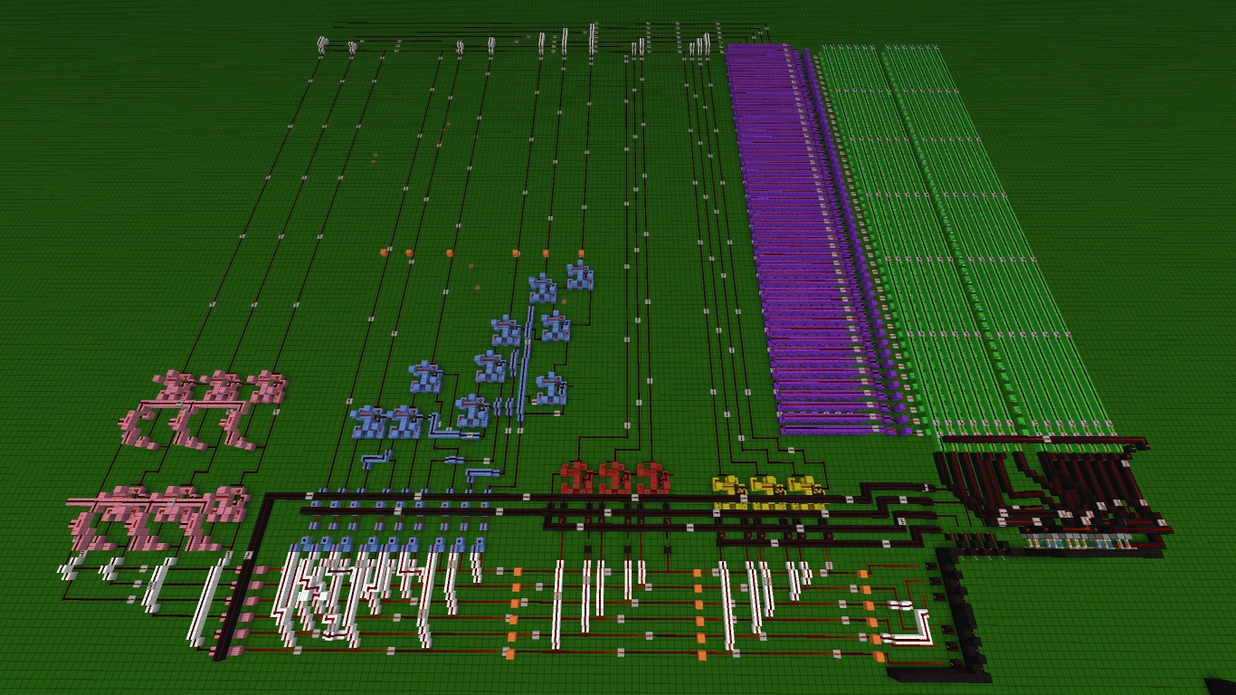
See the following image for an example of a calculator:
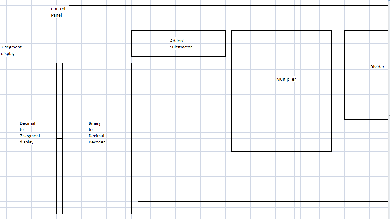
Calculator Plan
Calculator Scheme
Of course, all compilations are made with binary code. This is why this calculator has many different decoders.
Current parts[]
The following are the components of a calculator. They are in a somewhat logical order.
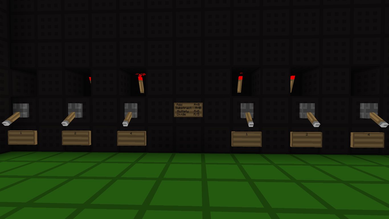
Control panel (room)[]
The control panel is the room from which you set the inputs and decide of the operation.
Numbers input panel[]
Numbers Input Panel
Here, the users will decide what numbers they want to use. In the picture, a lever-based binary input system is used, so the users must decompose the numbers they want to use into powers of two.
Operation panel[]
From this panel, the user chooses between the operations he is going to use: add (+), subtract (-), multiply (*) and divide (/). Like for the Number's Input Panel, this picture of the Operation Panel uses the lever system.
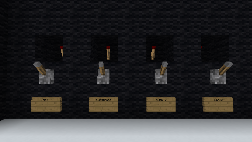
Operation Panel
Input wires (white and orange)[]
These wires link the input panel and the operation panel to the different logic units. Try to rearrange them in a manner where the same values go together. So, your wires should look like, from left to right: A1; B1; A2; B2; A4; B4; ...
Logic units[]
The logic units in a calculator are the machines that perform the operations.
Adder/Subtractor (yellow and red)[]
The picture to the left shows a version of an adder/subtractor. Its construction is simple because it is modulated (made of many same parts). That means that if you use more bits, you can just add more parts on the side. However, this means that you'll have to change some links.
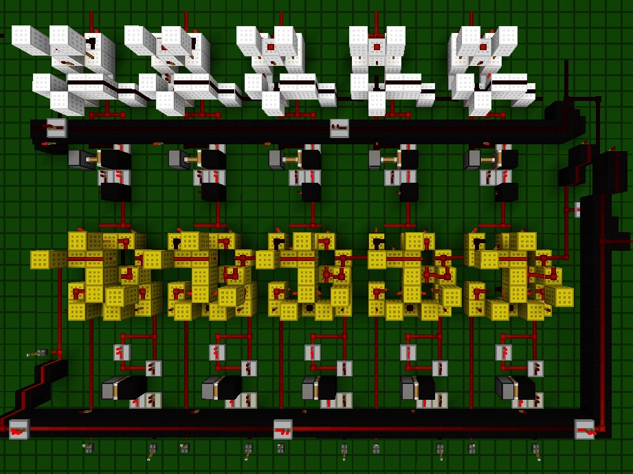

2-in-1 Adder/Subtractor
In this machine, your inputs (in binary code) go into the bottom (yellow) full adders. Each adder needs the two inputs (A and B) with the same values. Also, the least significant bit has to be on the left, so they should all be connected by their carries. Basically, your inputs look like the wires in the #Input Wires (white and orange) section. Use basic bridges to pass wires over the others without connecting them.
Your A inputs (left) are the minuend (X in X-Y=Z), and go straight in the adders. The B inputs, your subtrahend (Y in X-Y=Z), have to pass through a multiplexer, made out of a modified version of a XOR gate which gives to the adder an inverted signal in case of a subtraction. The multiplexer is controlled by a switch (on the picture, that switch is on the left). The sums go into another multiplexer, which, again, gives an inverted input in case of a subtraction. This is controlled by an IMPLIES gate (in the top right) which gives a true output if the switch is on "Subtraction" AND if the last carry is true. This is required because on a subtraction, that last carry actually means the "-" (minus) sign.
The white machines are half-adders, that use, as inputs, the carry of the last adder and the sum of their respective full adder. We need this because, if the answer is negative, it uses the equation " -A = !A (inverted A)+ 1 ", as explained here.
The final outputs are all of the top-most wires you can observe, plus the wire on the right (the carry from the last full adder) and the carry that goes in the first (left) half-adder, as the negation sign.
Multiplier (light blue)[]
The multiplier is probably the most complicated part of the calculator. For our purposes, multiplication is a repeated addition. That means that, once again, adders will be used here. Before you add the adders, you actually have to set up an AND gate (not including the control one). Its use is simple: in binary multiplication, because only 0's and 1's are used, the only way that we can have an output is by multiplying 1 by 1.
Here is how to construct a multiplier, in order from the least to the most significant bits.
Least significant bits :
1*1 = 1. That means that the output of the second AND gate (the control one) goes straight to the output collective wires.
Second to last:
1*2 = 2 and 2*1 = 2.
Those two outputs meet in a full adder. The sum goes to the output, and the carry goes to the next bit.
Next:
1*4 = 4; 2*2 = 4; and 4*1 = 4
The carry from the last bit goes in the first adder as the carry input. The two normal inputs are 2 of the 3 AND gates. The sum of this goes in a second adder, where the second input is the third AND gate. Both carry outs go to the next stage, and the sum goes to the output.
You continue like this until you run out of AND gates, or equations.
Divider (pink)[]
Dividers on a redstone calculator are less complicated than multipliers. Again, full adders should be used here. Basically, for each A input, set up n adders where n is the quantity of inputs by B. Also, this time, you have to "reverse them". Now the most significant bit should pass its carry downwards.
Output wires[]
Output wires have to get every output from every machine and redirect them to the next part using redstone dust.
Binary-to-decimal decoder[]
This transforms your binary code into a decimal output. The size of it will be (Binary inputs*2)*(Decimal output)
*Quick note* It uses a "programmable" XOR gate cane tend to a not gate. This activates a line of preset redstone torches to output the correct answer.
See also[]
- Redstone
- Mechanics/Redstone/Circuit
- Redstone clock
- Mechanics/Redstone/Logic circuit
- Mechanics/Redstone/Memory circuit
- Mechanics/Redstone/Pulse circuit
- Mechanics/Redstone/Transmission circuit
- Tutorials/Advanced redstone circuits
- Tutorials/Arithmetic logic
- Tutorials/Basic logic gates
- Tutorials/Hourly clock
- Tutorials/Redstone computers