A pulse circuit is a redstone circuit which generates, modifies, detects, or otherwise operates on redstone pulses.
Pulses[]
A pulse is a temporary change in redstone power that eventually reverts to its original state.
An on-pulse is when a redstone signal turns on, then off again. On-pulses are usually just called "pulses" unless there is a need to differentiate them from off-pulses.
An off-pulse is when a redstone signal turns off, then on again.
The pulse length of a pulse is how long it lasts. Short pulses are described in redstone ticks (for example, a "3-tick pulse" for a pulse that turns off 0.3 seconds after it turns on) while longer pulses are measured in any convenient unit of time (for example, a "3-second pulse").
The rising edge of a pulse is when the power turns on – the beginning of an on-pulse or the end of an off-pulse.
The falling edge of a pulse is when the power turns off – the end of an on-pulse or the beginning of an off-pulse.
Pulse logic[]
Pulse logic is a different approach to binary logic than standard redstone power binary (power present = 1, power absent = 0). In pulse logic, the pulse is a toggle of logic level of the contraption: (first pulse = 1, second pulse = 0). This approach allows implementing computational logic that operates not only on redstone signal, but also on block updates, and block positions; in particular implementation of mobile logical circuits in flying machines, and significant reduction of server-side lag through avoiding redstone dust, transporting signals through block updates instead - e.g. over Powered Rail. In many cases use of pulse logic also results in more compact circuitry, and allows building 1-tileable modules where classic redstone power would "spill" to the neighbor modules.
Conversion from classic redstone binary to pulse logic is performed through dual edge detectors, (usually just an Observer observing redstone dust or other power components), and conversion back is performed through T flip-flop circuits, in particular the block-dropping behavior of sticky pistons. That behavior is also utilized as memory storage in pulse logic, position of the block encoding state of memory cell.
Pulse interactions[]
Some redstone components react differently to short pulses:
- In Java Edition, a piston or sticky piston usually takes 1.5 ticks to extend. If the activation pulse ends before this (because it's only 0.5 ticks or 1 tick long), the piston or sticky piston "aborts" – it places the pushed blocks at their pushed position and return to its retracted state instantly. This can cause sticky pistons to "drop" their block – they push a block and then return to their retracted state without pulling it back.
- A redstone comparator does not always activate when given a pulse of 1 ticks or less.
- A redstone lamp can be deactivated only by an off-pulse of minimum 2 ticks.
- A redstone repeater does increase the length of pulses which are shorter than its delay to match its delay (for example, a 4-tick repeater changes any pulse shorter than 4 ticks into a 4-tick pulse).
- In Java Edition, a redstone torch cannot be activated by pulses shorter than 1.5 ticks.
Pulse analysis[]
When building circuits, it can sometimes be helpful to observe the pulses being produced to confirm their duration or spacing.
A pulse can be measured with 1-tick precision with an oscilloscope (see schematic, right).
An oscilloscope simply consists of a line of 1-tick repeaters (aka a "racetrack"). An oscilloscope should be constructed to be at least as long as the expected pulse, plus a few extra repeaters (the more repeaters, the easier it is to time capturing a pulse). For periodic pulses (as from clock circuits), an oscilloscope should be at least as long as the clock period (both the on and off parts of the pulse).
An oscilloscope can be frozen to aid reading by:
- using an oak sign next to the design.
- positioning the oscilloscope on the screen so that it can be viewed when the player pauses the game, or
- taking a screenshot with F2, or
- running repeaters into the side of the oscilloscope and powering them simultaneously to lock the repeaters of the oscilloscope.
An oscilloscope is not capable of displaying fractional-tick pulses directly (0.5-tick pulses, 1.5-tick pulses, etc.), but for fractional-tick pulses greater than 1 tick, the pulse length may appear to change as it moves through the oscilloscope. For example, a 3.5-tick pulse may sometimes power 3 repeaters and sometimes 4 repeaters.
Half-tick pulses do not vary between powering 0 or 1 repeaters (they just look like 1-tick pulses), but half-tick and 1-tick pulses can be differentiated with a redstone comparator – a 1-tick pulse can activate a comparator, but a half-tick pulse cannot in most cases.
Multiple oscilloscopes can be laid in parallel to compare different pulses. For example, you can determine a circuit's delay by putting the circuit's input signal through one oscilloscope and the circuit's output through another and counting the difference between the input and output signal edges.
Oscilloscopes are useful but sometimes require you to be in an inconvenient position to observe them. If you just need to observe the simultaneity of multiple pulses it can be useful to use pistons or note blocks and observe their movement or note particles from any angle. Redstone lamps are less useful for this purpose because they take 2 ticks to turn off.
Monostable circuit[]
A circuit is monostable if it has only one stable output state ("mono-" means "one", so "monostable" means "one stable state").
A circuit's output can be powered or unpowered. If an output stays in the same state until the circuit is triggered again, that output state is called "stable". An output state that changes without the input being triggered is not stable (that doesn't necessarily mean it's random – it may be an intentional change after a designed delay).
If a circuit has only one stable output state then the circuit is called "monostable". For example, if a powered state inevitably reverts to the unpowered state, but the unpowered state doesn't change until the input is triggered.
When someone says "monostable circuit" in Minecraft, they usually mean a pulse generator or a pulse limiter. However, any redstone circuit which produces a finite number of pulses is technically a monostable circuit (all the circuits in this article, in fact, as well as some others), so instead of saying monostable circuit, it can be helpful to be more specific:
- A pulse generator generates a pulse
- A pulse limiter reduces the duration of long pulses
- A pulse extender increases the length of short pulses
- A pulse multiplier produces multiple output pulses in response to a single input pulse
- A pulse divider produces an output pulse after a specific number of input pulses
- An edge detector produces an output pulse when it detects a specific edge of an input pulse
- A pulse length detector produces an output pulse when it detects an input pulse of a specific length
- A block update detector produces an output pulse when a specific block is updated (for example, stone is mined, water turns to ice, etc.)
- A comparator update detector produces an output pulse when a specific comparator is updated by an inventory update
Clock circuits also produce pulses, but they aren't monostable because they have no stable output states (they are "astable") unless forced into one by external interference (for example, when they're turned off). Logic and memory circuits aren't monostable because both of their output states are stable (they are "bistable") – they don't change unless triggered by their input.
Pulse generator[]
A pulse generator creates an output pulse when triggered.
Most pulse generators consist of an input and a pulse limiter. A pulse extender can be added on to generate a longer pulse.
Schematic Gallery: Pulse Generator
On-pulse Generator[]
Circuit Breaker Pulse Generator[]


Circuit Breaker Pulse Generator – Left: Sticky piston. Right: Regular piston. [schematic]
- 1×3×3 (9 block volume), 1-wide
- circuit delay: 1 tick
- output pulse: 1 tick
- The circuit breaker is one of the most commonly used pulse generator due to its small size and adjustable output.
- Variations: The output repeater may be set to any delay, which also lengthens the output pulse to equal the delay. When oriented north-south, the output repeater may be replaced by any mechanism component, causing the mechanism component to receive a 0 tick pulse.
Observer Pulse generator[]


common observer pulse generator
- 1×1×3 (3 block volume), 1-wide, 1 high, tileable
- circuit delay: 2 ticks
- output pulse: 1 tick
The observer pulse generator is one of the most common pulse generators due to its adaptability. It can be oriented in almost any direction, and the observer can be oriented in almost any direction, allowing for lots of flexibility. And depending on where the output is taken from, it can be a rising or falling edge pulse generator. The observer can also be updated by other circuitry to send more pulses from the output.
- Variations: The piston base can be oriented in any way; the same is true for the observer except for facing the piston itself. Output can be taken from either the extended or retracted position to change which edge it activates on.
Dust-Cut Pulse Generator[]


Dust-Cut Pulse Generator – [schematic]
- 1×4×3 (12 block volume), 1-wide
- circuit delay: 0 ticks
- output pulse: 1.5 ticks when the output is a piston, 1 tick for everything else
- A dust-cut pulse generator limits the output pulse by moving a block so that it cuts the output dust line.
NOR-Gate Pulse Generator[]


NOR-Gate Pulse Generator – [schematic]
- 1×4×3 (12 block volume), 1-wide, silent
- circuit delay: 2 ticks
- output pulse: 1 tick
- A NOR-gate pulse generator compares the current power to the power from 2 ticks ago – if the current power is on and the previous power was off, the output torch flashes on briefly.
- This design uses a trick to limit the output pulse to a single tick. A redstone torch cannot be activated by a 1-tick pulse from exterior sources, but a torch activated by a 2-tick exterior pulse can short-circuit itself into a 1-tick pulse. To increase the output pulse to 2 ticks, remove the block over the output torch. To then increase it to 3 ticks, increase the delay on the repeater to 4 ticks.
Locked-Repeater Pulse Generator[]


Locked-Repeater Pulse Generator – [schematic]
- 2×3×2 (12 block volume), flat, silent
- circuit delay: 2 ticks
- output pulse: 1 tick
- When the lever is turned off, the locked repeater allows a pulse through.
- Variations: The locked repeater and the input repeaters can be set to any delay. This increases the output pulse length, but also the circuit delay.
Comparator-Repeater Pulse Generator[]


Comparator-Repeater Pulse Generator - [schematic]
- 2×4×2 (15 block volume), flat, silent
- circut delay: 1 tick
- output pulse: 2 ticks
- The dust first powers the comparator, turning on the output, then the delayed pulse (with the repeater) shuts off the output.
- Variations: The repeater can be set to any number of ticks, increasing only the output pulse length.
Off-pulse Generator[]
An off-pulse generator has an output which is usually on, but generates an off-pulse when triggered.
OR-Gate Off-Pulse Generator[]


OR-Gate Off-Pulse Generator – [schematic]
- 1×3×3 (9 block volume), 1-wide, silent
- circuit delay: 1 tick
- output pulse: 1 tick (off)
- When triggered, the bottom torch turns off, but the top torch doesn't turn on until 1 tick later, allowing a 1-tick off-pulse output.
Pulse length limiter[]
A pulse limiter (aka "pulse shortener") reduces the length of a long pulse.
An ideal pulse limiter would allow shorter pulses through unchanged, but in practice the range of input pulse can often be determined (or guessed) and it is sufficient to use a circuit which produces a specific pulse shorter than expected input pulses.
Any rising edge detector can also be used as a pulse limiter.
Schematic Gallery: Pulse Limiter
- Circuit Breaker Pulse Limiter


Circuit Breaker Pulse Limiter – [schematic]
- 1×3×3 (9 block volume), 1-wide
- circuit delay: 1 tick
- output pulse: 1 tick
- The circuit breaker is the most commonly used pulse limiter due to its small size and adjustable output.
- Variations: The output repeater may be set to any delay, which also lengthens the output pulse to equal the delay. The output repeater may be replaced by any mechanism component, causing the mechanism component to receive a 0.5-tick activation pulse.
- Dust-cut pulse limiter


Dust-Cut Pulse Limiter – [schematic]
- 1×5×3 (15 block volume), 1-wide, instant
- circuit delay: 0 ticks
- output pulse: 1.5 ticks
- A dust-cut pulse limiter limits the output pulse by moving a block so that it cuts the output dust line.
- The dust-cut pulse limiter doesn't "repeat" its input (boost it back up to full power), so a repeater may be needed before or after it (adding delay).
- The dust-cut pulse limiter is an "ideal" pulse limiter (see above). Pulses shorter than 1.5 ticks (its maximum output pulse) are allowed through unchanged.
- Moved-block pulse limiter


Moved-Block Pulse Limiter – [schematic]
- 3×3×2 (12 block volume), flat
- circuit delay: 1 tick
- output pulse: 1 tick
- Uses the same principle as the circuit breaker pulse limiter – power the output through a block, then remove the block to keep the output pulse short.
- Variations: The bottom repeater can be set to a longer delay to produce output pulses of 2 or 3 ticks. The repeater powering the piston can be replaced with a comparator to generate a 0-tick pulse
- NOR-gate pulse limiter


NOR-Gate Pulse Limiter – (1-wide) [schematic]

NOR-Gate Pulse Limiter – Top: 1-tick. Bottom: Flat. [schematic]
- features vary (see schematics)
- A NOR-gate pulse limiter compares the current power to the power from 2 ticks ago – if the current power is on and the previous power was off, the output torch flashes on briefly.
- The "1-wide" and "1-tick" designs use a trick to limit the output pulse to a single tick. A redstone torch cannot be activated by a 1-tick pulse from exterior sources, but a torch activated by a 2-tick exterior pulse can short-circuit itself into a 1-tick pulse. Remove the block over an output torch to increase the output pulse to 2 ticks.
- Locked-repeater pulse limiter


Locked-Repeater Pulse Limiter – [schematic]
- 2×4×2 (16 block volume), flat, silent
- circuit delay: 3 ticks
- output pulse: 1 tick
- Uses repeater locking to shut pulses off after 1 tick.
- Variations: The output repeater can set to any delay. This increases the output pulse, but also increases the circuit delay.
- If the input doesn't have to be at the same height as the output, you can move the torch so that it's attached to the top of the block it's currently above, and run the input into that block (making the circuit only 2×3×2).
- Dropper-hopper pulse limiter


Dropper-Hopper Pulse Limiter – [schematic]
- 1×4×2 (8 block volume), 1-wide, flat, silent
- circuit delay: 3 ticks
- output pulse: 3.5 ticks
- When the input turns on, the dropper pushes an item into the hopper, activating the comparator until the hopper pushes the item back.
- The initial block is required to activate the dropper without powering it (which would deactivate the adjacent hopper, preventing it from returning the item to turn off the output pulse).
- Because the output comes from a comparator used as an inventory counter, the output power level is 1 (with a stackable item) or 3 (with a non-stackable item) – add a repeater for a higher power level output.
- Variations: If the input and output don't need to be at the same height, you can reduce the size of the circuit by putting the hopper on top of the dropper (making the circuit 1×3×2).
Off-pulse limiter[]
An off-pulse limiter (aka "inverted pulse limiter") has an output which is usually on, but which shortens the length of long off-pulses.
Any inverted falling edge detector can also be used as an off-pulse limiter.
- OR-gate off-pulse limiter

OR-Gate Off-Pulse Limiter – Top: 1-tick. Bottom: Flat. [schematic]


OR-Gate Off-Pulse Limiter – Instant. [schematic]
- features vary (see schematics)
- An or-gate off-pulse limiter combines the input with a delayed inverted input to limit off-pulses.
- The "instant" version doesn't repeat its input (boost it back up to full power), so a repeater may be needed before or after it (adding delay).
- Variations: The bottom repeater of the flat version can be adjusted to any delay, increasing the length of the off-pulse to match the repeater's delay (this doesn't actually increase the circuit delay).
- The bottom redstone dust in the "instant" version can be replaced with a repeater to increase the length of its off-pulse.
- Moving-block off-pulse limiter


Moving-Block Off-Pulse Limiter – [schematic]
- 1×4×2 (8 block volume), 1-wide, instant
- circuit delay: 0 ticks
- output pulse: 2.5 ticks (off, 3 if the output is a piston)
- When the input turns off, the piston begins to retract. 1 tick later, the torch turns on, which re-activates the sticky piston by quasi-connectivity, causing it to extend again.
Pulse extender[]
A pulse extender (a.k.a. "pulse sustainer", "pulse lengthener") increases the duration of a pulse.
The most compact options are:
- Up to 4 ticks: Repeater
- Up to 4 ticks per repeater: Repeater-Line Pulse Extender
- 1 second to 4 minutes: Dropper-Latch Pulse Extender or Hopper-Clock Pulse Extender
- 5 minutes to 81 hours: MHDC Pulse Extender
Schematic Gallery: Pulse Extender
- Redstone repeater
- 1×1×2 (2 block volume)
- 1-wide, flat, silent
- circuit delay: 1 to 4 ticks
- output pulse: 1 to 4 ticks
- For any input pulse shorter than its delay, a redstone repeater increases the duration of the pulse to match its delay. For example, a 3-tick repeater turns a 1-tick pulse or a 2-tick pulse into a 3-tick pulse.
- Additional repeaters only delay the pulse, not extend it (but see the repeater-line pulse extender below).
- Repeater-line pulse Extender


Repeater-Line Pulse Extender – Top: Delayed (1.4 second). Bottom: Instant (1 second). [schematic]
- 2×N×2
- flat, silent, instant
- circuit delay: 0 ticks (instant) or 4 ticks (delayed)
- output pulse: up to 4 ticks per repeater
- For the instant version, the input must be a pulse at least as long as the longest-delay repeater in the line (usually 4 ticks) – if not, use the delayed version.
- Dropper-latch pulse extender


Dropper-latch pulse extender – [schematic]
- 2×6×2 (24 block volume)
- flat, silent
- circuit delay: 5 ticks
- output pulse: 5 ticks to 256 seconds
- Each stackable item, 16-stackable item and unstackable item in the middle hopper adds 8 ticks (0.8 seconds), 32 ticks or 256 ticks to the output pulse respectively. The output pulse can be fine-tuned by increasing the delay on the 1-tick repeater by up to 3 ticks, decreasing the delay on the 4-tick repeater by up to 3 ticks, or by replacing the 4-tick repeater with a block to decrease the delay by 4 ticks (these adjustments affect the total pulse duration, not per item, allowing pulse durations of any tick amount from 5 ticks to 256 seconds).
- Variations: If the input pulse might be longer than half the output pulse, add a block before the dropper to keep it from deactivating the hopper. A 1-wide version is possible by using two droppers (adjustable only in increments of 8 ticks):
- Hopper-clock pulse extender

Hopper-Clock Pulse Extender – Top: 1-wide. Bottom: Flat. In both, the left piston is sticky and the right is regular. [schematic]
- features vary (see schematics)
- circuit delay: 1 tick
- output pulse: 4 ticks to 256 seconds
- A hopper-clock pulse extender is a hopper clock with one of the sticky pistons replaced with a regular piston so that it doesn't pull the block of redstone back, but instead wait for the input to trigger a new clock cycle.
- A hopper-clock pulse extender with a single item in its hoppers produces a 4-tick output pulse. Each additional item adds 8 ticks to the output pulse (unlike the dropper-latch pulse extender, the output of a hopper-clock pulse extender can be adjusted only in 8-tick increments).
- While waiting for the input to turn on, the sticky piston is actually in a state where it is powered but doesn't know it (like a stuck-piston BUD circuit) until "woken up" by the input changing its power level. This works as long as the input power level is different than the resting output of the powered comparator (unintuitively, it even works if the input power level is less than the comparator output).
- Caveats:
- - Any block or redstone update near the powered & stuck sticky piston can trigger it, so care should be taken to keep other circuit activity away from the sticky piston.
- - The timer/counter part starts after the rising edge of the input pulse. -> At worst the output pulse is only "input_pulse + extender_time/2" not "input_pulse + extender_time". For "input_pulse < extender_time/2" it's always just "extender_time".
- Earliest known publication: 4 May 2013 CodeCrafted: "Minecraft QASI: Compact adjustable pulse extender" (based on the ethonian hopper clock)
- RS latch pulse extender

RS NOR Latch Pulse Extender (3 seconds) – There is redstone dust under the raised block. [schematic]
- features vary (see schematics)
- output pulse: up to 8 ticks per repeater
- An RS latch pulse extender works by setting the output on with a latch, then resetting the latch after some delay.
- Both of the circuits below use a trick to double the delay produced by the repeaters, by first powering the output from the latch, then from the repeaters. This means that any 1-tick adjustment to the repeater loop produces a 2-tick adjustment in the output pulse.
- Fader pulse extender
Fader Pulse Extender (6 seconds) – [schematic]
- 2×N×2
- flat, silent
- circuit delay: 0 ticks
- output pulse: up to 14 ticks per comparator
- The delay depends on the input's signal strength – for input signal strength S, the delay is (S-1) ticks per comparator. The signal strength of the output gradually decays, so should usually be boosted with a repeater. Because this uses comparators, this pulse extender does not work with most 1 tick or shorter pulses.
- MHC pulse extender


MHC Pulse Extender – All pistons are sticky. [schematic]
- 6×6×2 (72 block volume)
- flat
- circuit delay: 3 ticks
- output pulse: up to 22 hours
- "MHC" stands for "multiplicative hopper clock" (a hopper counter multiplies the clock period of a hopper clock).
- When the input turns on, the torch turns off, allowing both clocks to cycle into a state where the bottom clock continues to hold the torch off until it's completed one full cycle. The number of items in the top hoppers determines the top clock's cycle period, and its block of redstone moves every half-cycle, allowing the bottom clock to move one item.
- The half-cycle is equal to the number of items in the top hoppers times 4 ticks (or 0.4 seconds per item) – up to 128 seconds for 320 items. The bottom clock keeps the output on for a number of half-cycles equal to twice the number of items in the bottom hoppers, minus 1. Thus, the output pulse equals 0.4 seconds × <top items> × (2 × <bottom items> - 1).
Items Required for Useful Output Pulses Output Pulse Items in top hoppers Items in bottom hoppers 5 minutes 150 3 10 minutes 300 3 15 minutes 150 8 20 minutes 200 8 30 minutes 300 8 1 hour 200 23 90 minutes 300 23 2 hours 240 38 3 hours 216 68 4 hours 288 63 6 hours 240 113 12 hours 288 188
- MHDC pulse extender


MHDC Pulse Extender – All pistons are sticky. [schematic]
- 5×7×2 (70 block volume)
- flat
- circuit delay: 5 ticks
- output pulse: up to 81 hours
- "MHDC" stands for "multiplicative hopper-dropper clock" (a dropper counter multiplies the clock period of a hopper clock).
- When the input turns on, the torch turns off, allowing both clocks to cycle into a state where the bottom clock continues to hold the torch off until it's completed one full cycle. The hoppers can hold up to 320 items (X) and the droppers can hold up to 576 items (Y). The duration of the output pulse is X × (2Y-1) × 0.8 seconds.
Items Required for Useful Output Pulses Output Pulse Items in hoppers Items in droppers 5 minutes 125 2 10 minutes 250 2 15 minutes 225 3 20 minutes 300 3 30 minutes 250 5 1 hour 300 8 90 minutes 270 13 2 hours 200 23 3 hours 300 23 4 hours 144 63 6 hours 216 63 12 hours 240 113 24 hours 288 188 48 hours 320 338 72 hours 288 563
- Cooldown pulse extender
- 1×4×2 (8 block volume)
- circuit delay: 3 ticks
- output pulse: up to 27 minutes
- This pulse extender uses a command block to slow the hopper transfer rate. The exact command depends on the direction the pulse extender is facing, but for a pulse extender facing the positive X direction it look something like this:
/data modify block ~2 ~ ~ TransferCooldown set value X, where X is the number of game ticks (up to 32,767) to hold the item in the hopper (20 game ticks = 1 second, lag permitting).
- When the command block is powered directly it activates the adjacent dropper, pushing the item into the hopper to power the output, and simultaneously changes the hopper's cooldown time to delay when it pushes the item back to the dropper.
Pulse multiplier[]
A pulse multiplier turns one input pulse into multiple output pulses.
There are three primary strategies for designing pulse multipliers:
- Split the input pulse into multiple paths that arrive at the output at different times
- Enable a clock to run while the input pulse is on
- Trigger a clock that runs for a finite number of cycles, independent of the input pulse length
In case the player requires only the pulse frequency to be doubled, usually a simple dual edge detector is often sufficient:
- Observer pulse doubler
- 1×1×1 (1 block), flat, silent, 1-tileable
- circuit delay: 1 tick
- output pulses: 2 1-tick pulses the length of input pulse apart.
- An observer watching the input signal (redstone dust, button, repeater set to 1 tick, etc) produces a pulse on each of the edges of the input, producing two 1-tick pulses on each edge of the input pulse, providing the input pulse is sufficiently long (3 redstone ticks minimum). If the pulse is shorter than this, a redstone lamp can be put infront of the observer to remedy this issue.
Schematic Gallery: Pulse Multiplier
Split-path pulse multiplier[]
A split-path pulse multiplier produces multiple pulses by splitting the input signal into multiple paths and having them arrive at the output at different times. This usually requires first reducing the length of the input pulse with a pulse limiter to reduce the delay required between each output pulse.
- Dispenser double-pulser


Dispenser Double-Pulser – [schematic]
- 1×6×3 (18 blocks), 1-wide
- circuit delay: 1 tick
- output pulses: 1 tick and 2 ticks
- This circuit is useful for double-pulsing a dispenser, to quickly dispense then retract water or lava. First it powers a block on one side of the dispenser, then the other side.
Enabled-clock pulse multiplier[]
An enabled-clock pulse multiplier runs a clock for as long as the input stays on, thus producing a number of pulses relative to the input pulse length.
- Subtraction 1-clock pulse multiplier


Subtraction 1-Clock Pulse Multiplier – [schematic]
- 2×3×2 (12 blocks), flat, silent
- circuit delay: 1 tick
- output pulses: 1 tick
- This pulse multiplier does not repeat its input signal, so may need a repeater before or after (increasing the circuit delay).
- This circuit produces 5 pulses when enabled with a stone button, or 7 pulses when enabled with a wooden button. For other number of pulses, consider a pulse extender to lengthen the input pulse.
- Subtraction N-clock pulse multiplier

Subtraction N-Clock Pulse Multiplier – [schematic]
- 2×3×2 (12 blocks), flat, silent
- circuit delay: 1 tick
- output pulses: 2+ ticks
- The output pulses are 1 tick longer than the delay set on the repeater (so, 2 to 5-tick output pulses). For even longer pulses, replace the dust next to the repeater with another repeater.
- This pulse multiplier does not repeat its input signal, so may need a repeater before or after (increasing the circuit delay).
- The table below shows the number of output pulses produced with various combinations of button inputs and repeater delays (for more pulses, consider a pulse extender to lengthen the input pulse):
Repeater Delay Stone Button Wooden Button 1 tick 3 pulses 4 pulses 2 ticks 2 pulses 3 pulses 3 ticks 2 pulses 2 pulses 4 ticks 1 pulse 2 pulses
- Torch-repeater N-clock pulse multiplier


Torch-Repeater N-Clock Pulse Multiplier – [schematic]
- 2×4×2 (16 blocks), flat, silent
- circuit delay: 2 ticks
- output pulses: 3+ ticks
- The output pulses are 1 tick longer than the delay set on the repeater (so, 3 to 5-tick output pulses). The repeater can't be set to a 1-tick delay or the right torch burns out (which could be useful for limiting the number of pulses to 8 maximum).
Triggered-clock pulse multiplier[]
A triggered-clock pulse multiplier consists of a clock circuit that is allowed to run for a specific number of cycles once triggered. Strategies for designing a triggered-clock pulse multiplier include using a latch to turn the clock on and have the clock itself reset the latch back off after one or one-half clock cycles, or using a pulse extender to run a clock.
- Dropper-latch 2-clock pulse multiplier


Dropper-Latch 2-Clock Pulse Multiplier – The top dropper contains a single item. The bottom dropper contains a number of items equal to the desired pulse count. [schematic]
- 3×4×2 (24 blocks), flat, silent
- circuit delay: 3 ticks
- output pulses: 1 to 320 2-tick pulses
- This pulse multiplier produce one 2-tick pulse for every item placed in the bottom dropper (with a 2-tick off-pulse between each on-pulse).
- After it has finished its pulses, it requires a reset time equal to 0.4 seconds × pulse count. If it is reactivated during this time, it produces fewer pulses.
- If the input pulse is longer than the output pulses, the powered dropper prevents the clock from turning off because the disabled hopper can't push its item back. If a long input pulse is possible, place a solid block between the input and the dropper so that it activates without being powered.
- Earliest known publication: 4 September 2013[1]

Dropper-Latch 2-Clock Pulse Multiplier (Updated) Added a repeater for the lower hopper to compensate and lock the items while active
As of 1.11, it the lower hopper needs a longer pulse from the clock.
To compensate, we add a repeater facing down to a block next to the, now below the dropper, hopper, and set it to 3 ticks.
If you want a longer clock, use the formula:
2n - 1where n is the clock pulse, for the delay of the lower repeater
- Dropper-latch 1-clock pulse multiplier


Dropper-Latch 1-Clock Pulse Multiplier – The dropper contains a single item. The middle hopper contains one or more items depending on the desired pulse count (the first and last items should be non-stackable items). [schematic]
- 2×9×2 (36 blocks), flat, silent
- circuit delay: 5 ticks
- output pulses: 2 to 777 1-tick pulses
- This pulse multiplier allows a wide range of pulses, with no reset time required.
- The first and last items placed in the middle hopper should be non-stackable items (to give the output enough signal strength to run the subtraction clock). Up to three stacks of stackable items may be placed between the two non-stackable items.
- The circuit produces four 1-tick pulses for every item placed in the middle hopper (with a 1-tick off-pulse between each on-pulse). The total number of pulses may be reduced by 1 by changing the 4-tick repeater to 2 ticks, or reduced by 2 by replacing the 4-tick repeater with a block, or increased by 1 by changing the 1-tick repeater to 3 ticks.
- If the input pulse is longer than the output pulses, the powered dropper prevents the clock from turning off because the disabled hopper can't push its item back. If a long input pulse is possible, place a solid block between the input and the dropper so that it activates without being powered.
Pulse divider[]
A pulse divider (a.k.a. "pulse counter") produces an output pulse after a specific number of input pulses – in other words, it turns multiple input pulses into one output pulse.
Because a pulse divider must count the input pulses to know when to produce an output pulse, it has some similarity to a ring counter (an n-state memory circuit with only one state on). The difference is that a ring counter's output state changes only when its internal count is changed by an input trigger, while a pulse divider produces an output pulse and then returns to the same unpowered output it had before its count was reached (in other words, a pulse divider is monostable but a ring counter is bistable). Any ring counter can be converted into a pulse divider just by adding a pulse limiter to its output (making it monostable).
In addition to the circuits here, a clock multiplier can function as a pulse divider (or a ring counter, for that matter); unlike these circuits, its output remains ON until the next input pulse turns it off.
Schematic Gallery: Pulse Divider


Hopper-Loop Pulse Divider – [schematic]
- Hopper-loop pulse divider
-
- 2×(3 + pulse count/2)×3
- output pulse: 3 ticks
- This is a hopper-loop ring counter with an incorporated pulse limiter on the output.
- Each input pulse turns the redstone dust off for 1 tick, allowing the item to move to the next hopper. When the item reaches the dropper it turns on the output briefly, until the redstone dust turning back on activates the dropper to push the item to the next hopper.
- To count an even number of pulses, replace another hopper with a dropper. Putting the second dropper right before the first dropper changes the output pulse to 6 ticks.
- The output is signal strength 1 or 3 (with a stackable or non-stackable item in the hoppers) so may need to be boosted with a repeater.
- Variations: Removing the dust from on top of the dropper and replacing the dropper with a hopper increases the output pulse to 4 ticks but makes the entire circuit silent.
- Dropper-hopper pulse divider


Dropper-Hopper Pulse Divider – The dropper contains a number of items equal to the pulse count. The bottom-left hopper contains a single item. [schematic]
- 3×4×2 (24 block volume)
- flat
- output pulse: (4 × pulse count) ticks
- The dropper-hopper pulse divider can count up to 320 pulses.
- Each input pulse pushes an item from the dropper to the hopper next to it. When the dropper is finally emptied, its comparator turns off, allowing the item in the bottom-left hopper to move to the right, starting the reset process. When the top hopper has finished moving items back to the dropper, the item in the bottom hoppers moves back to the left, ending the reset process.
- Once it has begun its output pulse, the pulse divider goes through a reset period of (4 × pulse count) ticks (the same length as the output pulse). Any new input pulses during the reset period is not counted, but only extends the reset period. Because of this reset period, this pulse divider is best when the typical interval between input pulses is greater than the reset period, or you can run a line back from the output to suppress inputs while it is resetting.
- The output is signal strength 1 or 3 (with a stackable or non-stackable item in the bottom hoppers) so may need to be boosted with a repeater. The output pulse length is also proportional to the pulse count, so may need to be shortened with a pulse limiter.
- Dropper-dropper pulse divider


Dropper-Dropper Pulse Divider – The left dropper contains a number of items equal to the pulse count. The left hopper contains a single non-stackable item. [schematic]
- 3×6×2 (36 block volume)
- flat
- output pulse: (2 × pulse count) ticks
- The dropper-dropper pulse divider can count up to 576 pulses.
- Each input pulse pushes an item from the left dropper to the right dropper. When the left dropper is finally emptied, its comparator turns off, allowing the item in the bottom-left hopper to move to the right, starting the subtraction 1-clock driving the reset process (although the subtraction clock pulses the dropper, the circuit's output alternates only in signal strength, staying on the whole time – subtraction clocks can be tricky that way!). When the right dropper has finished moving items back to the left dropper, the item in the bottom hoppers moves back to the left, ending the reset process.
- Once it has begun its output pulse, the pulse divider goes through a reset period of (2 × pulse count) ticks (the same length as the output pulse). Any new input pulses during the reset period is not counted, but only extends the reset period. Because of this reset period, this pulse divider is best when the typical interval between input pulses is greater than the reset period, or you can run a line back from the output to suppress inputs while it is resetting.
- The output alternates between signal strength 1 and 3 so may need to be boosted with a repeater. The output pulse length is also proportional to the pulse count, so may need to be shortened with a pulse limiter.
- Inverted binary divider or counter

Binary Counter (Tall) – Three dividers stacked to make an 8-counter. [schematic]

Binary Counter with Reset [schematic]
- 3×5×2 (30 block volume)
- flat, silent, 3-wide stackable (alternating)
- input: 2 off-ticks, use a pulse limiter if necessary
- output pulse: 2 off-ticks
- delay: 3 ticks (per unit in stack)
- The inverted binary divider or counter uses the latching feature of redstone repeaters to create a two-state (binary) counter. Multiple counters can be stacked to construct an n-bit counter, giving 2n input pulses per output pulse. It is called 'inverted' because it counts the number of off pulses, rather than on-pulses. Note that it triggers every two off-ticks, so holding the input low causes it to count multiple times then burn out a redstone torch. You may want to use a pulse limiter on the input signal to prevent this.
- Used purely as a pulse divider or counter this circuit is somewhat inefficient, since it would have to be stacked nine times to be able to count almost as many pulses (512) as the dropper-dropper divider. However, the stacking binary design means that the pulse count value can be easily read out by simply taking an output line from each stack element. In combination with OR or NOR gates, this can be used to trigger an output after an arbitrary number of pulses, or to create a divider for any number when combined with the reset circuit below.
- 'Tall' binary counter
- 2×5×3 (30 block volume)
- silent, 2-wide stackable (alternating)
- Functionally the same as the flat (3×5×2) binary counter, but takes one extra vertical block and one less horizontally, which may be an advantage when stacking them together. Requires an extra torch compared to the flat circuit.
- Binary counter reset circuit
- Adding this to the binary counter circuit allows it to be reset at any time; this can be used to create a counter for any desired number, or even a programmable counter (with extra circuits to select the number). This can be applied to either version, though the schematic shows it connected to the 'tall' version.
- Like the counter itself, the reset circuit is active low; it requires at least three off-ticks to perform the reset, although the actual reset does not take place until the rising edge (end) of the off-pulse. (A standard button followed by an inverter works fine, as seen in the screenshot.)
- 1-tick binary counter/divider [Java Edition only]
- 1×3×2n+1 (1-tick input) or 1×3×2n+3 (for input longer than 1 tick)
- 1-wide, tileable
- 2n divider
- output pulse: 1-4 ticks
- A cheap, noisy option to output 1 out of 2n pulses (1 in 2, 4, 8, 16, 32 etc.), indefinitely extensible - each next module (repeater-piston pair) doubling the divider. Depends on the Java Edition's quirk of sticky pistons 'spitting out' their payload when activated with 1-tick pulses and quasi-connectivity. If the input pulse is longer than 1 tick, the first module acts as pulse limiter instead of a 'memory cell', so the only modification needed for this sort of input is adding one more module vs 1-ticked input (e.g. from an observer). The output pulse can be extended up to 4 ticks by increasing the tick count on the last repeater.
- Use as a binary counter requires reading position of the blocks moved by the pistons, e.g. through repeaters one block above the 'rest' position.
- If the input has mixed length pulses, both 1-tick and longer, set the first repeater to 2 ticks and treat the first piston as pulse limiter, not counter module.
Edge detector[]
| Circuit | Rising Edge | Falling Edge |
|---|---|---|
| Rising Edge Detector | On-pulse | n/a |
| Falling Edge Detector | n/a | On-pulse |
| Dual Edge Detector | On-pulse | On-pulse |
| Inverted Rising Edge Detector | off-pulse | n/a |
| Inverted Falling Edge Detector | n/a | off-pulse |
| Inverted Dual Edge Detector | off-pulse | off-pulse |
An edge detector outputs a pulse when it detects a specific change in its input.
- A rising edge detector outputs a pulse when the input turns on.
- A falling edge detector outputs a pulse when the input turns off.
- A dual edge detector outputs a pulse when the input changes.
An inverted edge detector is usually on, but outputs an off-pulse (it turns off, then back on again) when it detects a specific change in its input.
- An inverted rising edge detector outputs an off-pulse when the input turns on.
- An inverted falling edge detector outputs an off-pulse when the input turns off.
- An inverted dual edge detector outputs an off-pulse when the input changes.
Rising edge detector[]
A rising edge detector (RED) outputs a pulse when its input turns on (the rising edge of the input).
Any rising edge detector can also be used as a pulse generator or pulse limiter.
Schematic Gallery: Rising Edge Detector
- Circuit breaker
Circuit Breaker – [schematic]
- 1×3×3 (9 block volume)
- 1-wide
- circuit delay: 1 tick
- output pulse: 1 tick
- The circuit breaker is one of the most commonly used rising edge detector due to its small size and adjustable output.
- Variations: The output repeater may be set to any delay, which also lengthens the output pulse to equal the delay. When oriented north-south, the output repeater may be replaced by any mechanism component, causing the mechanism component to receive a 0-tick activation pulse.
- Moved observer RED

Moved Observer RED variants (vertical, straight, angled)
- 1x1x3, 1x1x1, 1x2x2
- 1-wide, 1-wide flat, flat
- circuit delay: Java: 2 ticks, Bedrock: 4 ticks
- output pulse: 1 tick
This observer pulse edge detector is one of the most common edge detectors due to its modifyablity. It can be oriented in almost any direction, and the observer can be oriented in almost any direction, allowing for lots of flexibilty. And depending on where the output is taken from, it can be a rising or falling edge pulse generator. The observer can also be updated by other circiutry to send more pulses from the output.
- Variations: The piston base can be oriented in any way, the observer can be oriented in any way except for facing the piston. Output can be taken from either the extended or retracted postion to change which edge it activates on.
- Works both with standard binary and pulse logic. [Java Edition only]
- Dust-cut rising edge detector
Dust-Cut RED (Unrepeated) – [schematic]


Dust-Cut RED (Repeated) – [schematic]
- 1×5×3 (15 block volume)
- 1-wide, instant
- circuit delay: 0 ticks ("Unrepeated") or 1 tick ("Repeated")
- output pulse: 1 tick, 1.5 ticks if the output is a piston
- A dust-cut rising edge detector works by moving a block so that it cuts the output dust line after only one tick.
- Because of the output's fractional length, a 1-tick repeater may be needed to force a sticky piston to drop its block.
- Subtraction rising edge detector


Subtraction RED (Unrepeated) – [schematic]


Subtraction RED (Repeated) – [schematic]
- 2×4×2 (16 block volume)
- flat, silent
- circuit delay: 1 tick ("Unrepeated") or 2 ticks ("Repeated")
- output pulse: 1 tick
- A subtraction rising edge detector works by using the subtraction mode of a redstone comparator to shut off the output pulse.
- This design uses a trick to limit the output pulse to a single tick. A comparator can't produce a 1-tick pulse by subtraction from an exterior source (such as if the repeater was set to a 1-tick delay), but if the external source would usually produce a 2-tick pulse or more, the comparator can short-circuit itself into a 1-tick pulse by incorporating it into a subtraction 1-clock (the block and parallel dust after the comparator), but allowing the clock to run for only one cycle.
- Variations: Remove the final block and dust to increase the output pulse to 2 ticks. Then increase the delay on the subtraction repeater to increase the output pulse length further.
- Earliest known publication: 7 January 2013 (basic concept)[2] and 3 May 2013 (1-tick output refinement)[3]
- Locked-repeater rising edge detector
Locked-Repeater RED (Corner) – [schematic]

Locked-Repeater RED (In-line) – [schematic]
- 2×4×2 (16 block volume)
- flat, silent
- circuit delay: 3 ticks
- output pulse: 1 tick
- Uses repeater locking to shut pulses off after 1 tick.
- Variations: If the input doesn't have to be at the same height as the output, you can move the torch so that it's attached to the top of the block it's currently above, and run the input into that block.
- Dropper-hopper rising edge detector
Dropper-Hopper RED – [schematic]
- 1×4×2 (8 block volume)
- 1-wide, silent
- circuit delay: 3 ticks
- output pulse: 3.5 ticks
- When the input turns on, the dropper pushes an item into the hopper, activating the comparator until the hopper pushes the item back.
- The initial block is required to activate the dropper without powering it (which would deactivate the adjacent hopper, preventing it from returning the item to turn off the output pulse).
- Because the output comes from a comparator used as an inventory counter, the output power level is 1 (with a stackable item) or 3 (with a non-stackable item) – add a repeater for a higher power level output.
- Variations: You can reduce the size of the circuit by putting the hopper on top of the dropper.
- Moved-block rising edge detector
Moved-Block RED – [schematic]
- 3×3×2 (18 block volume)
- flat
- circuit delay: 1 tick
- output pulse: 1 tick
- Uses the same principle as the circuit breaker – power the output through a block, then remove the block to keep the output pulse short.
- Variations: To increase the output pulse length, increase the delay on the repeater powering the piston. To get a 0-tick pulse, replace the repeater powering the piston with a comparator
- Other variations start with the piston powered. The output of the "offset" variation is weakly-powered and requires a repeater or comparator to do anything other than activate a mechanism component.

Moved-Block RED (In-line)

Moved-Block RED (Offset)


- NOR-gate rising edge detector
NOR-Gate RED – [schematic]
- 1×4×3 (12 block volume)
- 1-wide, silent
- circuit delay: 2 ticks
- output pulse: 1 tick
- A NOR-gate rising edge detector compares the current power to the power from 2 ticks ago – if the current power is on and the previous power was off, the output torch flashes on briefly.
- All of these designs use a trick to limit the output pulse to a single tick. A redstone torch cannot be activated by a 1-tick pulse from exterior sources, but a torch activated by a 2-tick exterior pulse can short-circuit itself into a 1-tick pulse. Remove the block over an output torch to increase the output pulse to 2 ticks.
Falling edge detector[]
A falling edge detector (FED) outputs a pulse when its input turns off (the falling edge of the input).
Schematic Gallery: Falling Edge Detector
- Dust-cut falling edge detector


Dust-Cut FED – [schematic]
- 1×4×3 (12 block volume)
- 1-wide, instant
- circuit delay: 0 ticks
- output pulse: 2 ticks
- When the input turns off, the piston immediately retracts the block, allowing the still-powered repeater to output a signal for 2 ticks. When the input turns on again, the piston cuts the connection before the signal can get through the repeater.
- Moved-block falling edge Detector


Moved-Block FED – [schematic]
- 1×3×3 (9 block volume)
- 1-wide
- circuit delay: 1 ticks
- output pulse: 1 ticks
- For some directions and input methods, the repeater may be needed to be set to 3 ticks to operate mechanism components.
- Earliest known publication: 27 May 2013[6]
- Moved-observer FED

Moved Observer FED - 1-wide
- 1×2×3 (6 block volume)
- 1-wide
- circuit delay: Java: 2 ticks, Bedrock: 4 ticks
- output pulse: 1 tick
- This circuit uses a sticky piston and an observer to separate the rising from the falling edge of a signal. The rising edge powers the piston, lifting the observer above the redstone where it has no effect. Then, at the falling edge of the input signal, the piston retracts and the observer sends a 1-tick pulse via the redstone on the glass block. Note that the glass block is required to prevent this from turning into a clock.
-

Moved Observer FED - flat

- Variations: The piston base can be oriented in any way, the observer can be oriented in any way except for facing the piston. Output can be taken from either the extended or retracted postion to change which edge it activates on.
- Locked-hopper falling edge detector


Locked-Hopper FED – [schematic]
- 1×4×2 (8 block volume)
- 1-wide, silent
- circuit delay: 1 tick
- output pulse: 4 ticks
- When the input turns off, it takes 1 tick for the torch to turn back on, giving hopper A a chance to push its item to the right and activate the output.
- This circuit requires time to reset (to push the item back into hopper A), so the fastest input clock it can handle is a 4-clock.
- Because the output comes from a comparator used as an inventory counter, the output power level is 1 (with a stackable item) or 3 (with a non-stackable item). Add a repeater for a higher power level output.
- Variations: This circuit can be snaked around in many different ways as long as the input dust is able to deactivate the first hopper.
- Earliest known publication: 22 May 2013[7]
- Locked-repeater falling edge detector

Locked-Repeater FED – [schematic]
- 2×3×2 (12 block volume)
- flat, silent
- circuit delay: 2 ticks
- output pulse: 1 tick
- When the input turns on, the output repeater is locked before it can be powered by the block behind it. When the input turns off, the output repeater is unlocked and is briefly powered by the block behind it, producing a 1-tick output pulse.
- Variations: Increase the delay on the output repeater to increase the output pulse length (up to 4 ticks), but also the circuit delay.
- Subtraction falling edge detector


Subtraction FED – [schematic]
- 2×5×2 (20 block volume)
- flat, silent
- circuit delay: 1 tick
- output pulse: 1 tick
- This design uses a trick to limit the output pulse to a single tick. A comparator can't produce a 1-tick pulse by subtraction from an exterior source (such as if the repeater was set to a 1-tick delay), but if the external source would usually produce a 2-tick pulse or more, the comparator can short-circuit itself into a 1-tick pulse by incorporating it into a subtraction 1-clock (the block and parallel dust after the comparator), but allowing the clock to run for only one cycle.
- Variations: Remove the final block and the dust next to it for a 2-tick pulse, then increase the delay on the repeater for a 3 or 4-tick pulse.
- NOR-gate falling edge detector


NOR-Gate FED – [schematic]
- 2×4×3 (24 block volume)
- silent
- circuit delay: 1 tick
- output pulse: 1 tick
- This circuit compares the current power to the power from 2 ticks ago – if the current power is off and the previous power was on, the output torch flashes on briefly.
- This designs uses a trick to limit the output pulse to a single tick. A redstone torch cannot be activated by a 1-tick pulse from exterior sources, but a torch activated by a 2-tick exterior pulse can short-circuit itself into a 1-tick pulse.
- Variations: Remove the block over the output torch to increase the output pulse to 2 ticks, then increase the delay on the repeater to increase the output pulse further.
- Observer FED / RED


Observer FED - flat – [schematic]


Observer FED - 1-wide


Observer FED - tileable
- 2x4x2, 1×4×3 or 1x5x3 (16, 12 or 15 block volume)
- 1-wide or flat, silent (tileable)
- circuit delay: 2 or 5 rs-tick (afaik)
- output pulse: 1 rs-tick
- For some reason the observer in this circuit (only) triggers when the input turns off. It works in Java version 1.17.1 thou I'm not sure why (Redstone torch and repeater have the same delay, don't they?).
- The "trick" is to keep the same distance between the observer to the repeaters output and the torch. Thus the power level in front of the observer always stays the same and yet the observer triggers on one of the two input changes.
- Variations:
- - Both flat and 1-wide versions allow for four different observer orientations.
- - Increase the repeater delay of the non-tileable variants to turn this FED into a RED.
- - The blue block in the tileable version is an inverted input to turn it into a RED.
- (by Nilbadimo)
Dual edge detector[]
A dual edge detector (DED) outputs a pulse when its input changes (at either the rising edge or the falling edge of the input). The simplest way to do is using an observer.
Schematic Gallery: Dual Edge Detector
- Moving-block dual edge detector
- The block of redstone moves when the signal turns on and when it turns off. While it is moving it cannot power the redstone dust, so the output torch turns on until the block of redstone stops moving.
- In the 1-wide version the block over the output torch short-circuits it into a 1-tick pulse – remove the block and take the output directly from the torch to increase the output pulse to 1.5 ticks. To get an output on the same side as the input, the torch can be placed on the other side of the bottom blocks (but without the block above it, which would clock the piston). The piston and block of redstone can be moved to the side of the dust, rather than on top of the dust, producing a shorter but wider circuit.
- Earliest known publication: 28 January 2013[8]
- Dust-cut dual edge detector
-
- features vary (see schematics)
- The simple version splits the difference between a rising edge detector and a falling edge detector to produce an output of 1 tick on each edge. The instant version adds an unrepeated rising edge detector to reduce the rising edge circuit delay to 0 ticks.
- Locked-repeater dual edge detector
-
- features vary (see schematics)
- A locked-repeater dual edge detector uses the timing of repeater locking to detect signal edges.
- The nor-gate design uses a trick to limit the output pulse to a single tick. A redstone torch cannot be activated by a 1-tick pulse from exterior sources, but a torch activated by a 2-tick exterior pulse can short-circuit itself into a 1-tick pulse. Remove the block over the output torch (and the dust on the block it's attached to) to increase the output pulse to 3 ticks.
- Earliest known publication: 16 April 2013 (NOR-gate locked-repeater FED)[9] and 1 May 2013 (OR-gate locked-repeater FED)[10]
- Piston OR-gate dual edge detector
- 3×4×2 (24 block volume)
- flat
- circuit delay: 1.5 ticks
- output pulse: 1.5 ticks
- A piston OR-gate dual edge detector moves a block between repeaters that change states shortly after the piston moves. This causes a pulse to be sent to a wire behind the moving block.
- Subtraction dual edge detector
-
- features vary (see schematics)
- A subtraction dual edge detector powers a comparator with an ABBA circuit, cutting the pulse short with subtraction.
- Earliest known publication: 3 August 2013[11]
- Twin NOR-gate dual edge detector
The most trivial way to build a dual edge detector is to OR the outputs of a NOR-gate rising edge detector and a NOR-gate falling edge detector. A useful feature of this approach is that you get the rising- and falling-only pulses for free if you need them. If rsource or space usage is more important than timing, parts of the components of the 2 single edge detectors can be shared (the middle row of the example in the Schematic Gallery: Dual Edge Detector). Again, the blocks above the torches limit the output pulse to 1 tick.
Inverted rising edge detector[]
An inverted rising edge detector (IRED) is a circuit whose output is usually on, but which outputs an off-pulse on the input's rising edge.
Schematic Gallery: Inverted Rising Edge Detector
- OR-gate inverted rising edge detector


OR-Gate IRED – [schematic]
- 1×3×3 (9 block volume)
- 1-wide, silent
- circuit delay: 1 tick
- output pulse: 1 to 3 ticks (off-pulse)
- An OR-gate inverted rising edge detector compares the current and previous input – if the current input is on and the previous input was off, the output turns off for a brief period.
- Variations: The "adjustable" version takes up the same space, but its output pulse can be adjusted from 1 to 3 ticks. The "flat" version can also be adjusted from 1 to 3 ticks.

OR-Gate IRED (Adjustable)
OR-Gate IRED (Flat)


.png)
.png)
.png)
.png)
.png)
.png)
.png)
.png)
.png)
.png)
- Earliest known publication: 1 June 2013[12]
- Moving-block inverted rising edge detector


Moving-Block IRED – [schematic]
- 1×4×3 (12 block volume)
- 1-wide, instant
- circuit delay: 0.5 ticks
- output pulse: 1 tick (off-pulse)
- This is a moving-block inverted dual edge detector with a repeater added to suppress the output on the falling edge.
- Dropper-hopper inverted rising edge detector
- 1×3×3 (9 block volume)
- 1-wide, silent
- circuit delay: 3 ticks
- output pulse: 4 ticks (off-pulse)
- When the input turns on, the dropper pushes the item up into the hopper, deactivating the comparator until the hopper pushes the item back down.
- The initial block is required to activate the dropper without powering it (which would deactivate the adjacent hopper, preventing it from returning the item to turn the output pulse back on).
- Because the output comes from a comparator used to measure inventory, the output power level is 1 (with a stackable item) or 2 (with a non-stackable item) – add a repeater for a higher power level output.
- Variations: The input block can be moved to the side of or underneath the dropper, and the hopper can be moved to the side of the dropper.
Inverted falling edge detector[]
An inverted falling edge detector (IFED) is a circuit whose output is usually on, but which outputs an off-pulse on the input's falling edge.
Schematic Gallery: Inverted Falling Edge Detector
- OR-gate inverted falling edge detector
-
- features vary (see schematics below)
- The input has two paths to the output, timed so that the output blinks off briefly when the input turns off.
- Moved-block inverted falling edge detector
Moved-Block IFED – [schematic]
- 1×4×2 (8 block volume), 1-wide, instant
- circuit delay: 0 ticks, output pulse: 2.5 ticks (off-pulse)
- Earliest known publication: 4 June 2013[13]
- Locked-repeater inverted falling edge detector
-
- 2×3×2 (12 block volume), flat, silent
- circuit delay: 2 ticks, output pulse: 1 tick (off-pulse)
- When the input turns on, the output repeater is locked before it can turn off. When the input turns off, the output repeater is unlocked and is briefly un-powered by the block behind it, producing a 1-tick output off-pulse.
Inverted dual edge detector[]
An inverted dual edge detector (IDED) is a circuit whose output is usually on, but which outputs an off-pulse when its input changes.
Schematic Gallery: Inverted Dual Edge Detector
- Moving-block inverted dual edge detector
-
- 1×3×3 (9 block volume), 1-wide, instant
- circuit delay: 0 ticks, output pulse: 1.5 ticks (off-pulse)
- Variations: The piston and block of redstone can be moved to the side of the dust, rather than on top of the dust, producing a flat 2-wide circuit.
- The sticky piston can be oriented vertically if the redstone dust is run around the side in a 2×2×4 configuration.
- OR-gate inverted dual edge detector
-
- 3×4×2 (24 block volume), flat, silent
- circuit delay: 2 ticks, output pulse: 3 ticks (off-pulse)
- Uses the timing of repeater locking to detect pulse edges.
- Slime BUD inverted dual edge detector
-
- 1×3×4 (12 block volume)
- circuit delay: instant, output pulse: 1 tick (off-pulse)
- The Slime BUD made possible by Minecraft 1.8 works great as an instant inverted dual-edge detector. Simply put a block of obsidian, a hopper, afurnace, etc. right next to the slime block, and run redstone from its top to your output, and put a piece of redstone dust on the same plane as the piston, with one block space between. That's your input.
- Variations: move the obsidian (or whatever you used) -- and the redstone on top of it -- up one block to get a normal (non-inverted) dual edge detector, but with 1.5 ticks delay.
Pulse length detector[]
Sometimes it is useful to be able to detect the length of a pulse generated by another circuit, and specifically whether it is longer or shorter than a given value. This has many uses, such as special combination locks (where the player have to hold down the button), or detecting Morse code.
- Long pulse detector
- 2×6×3 (36 block volume)
- silent
- To test for a long pulse, we use an AND gate between the beginning and end of a line of redstone repeaters. These allow the signal to pass through only if it has a signal length longer than the delay of the repeaters. A pulse that does get through is shortened by the delay amount, possibly down to 1 tick.
- Long pulse detector
- 2×5×2 (20 block volume)
- flat
- Similar to the design above, but using a piston-based AND gate which shuts off the output as soon as the input turns off.
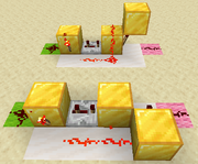
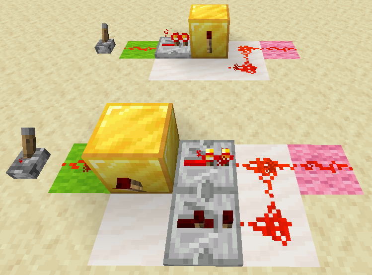
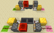
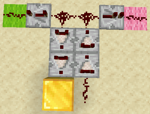
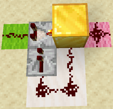
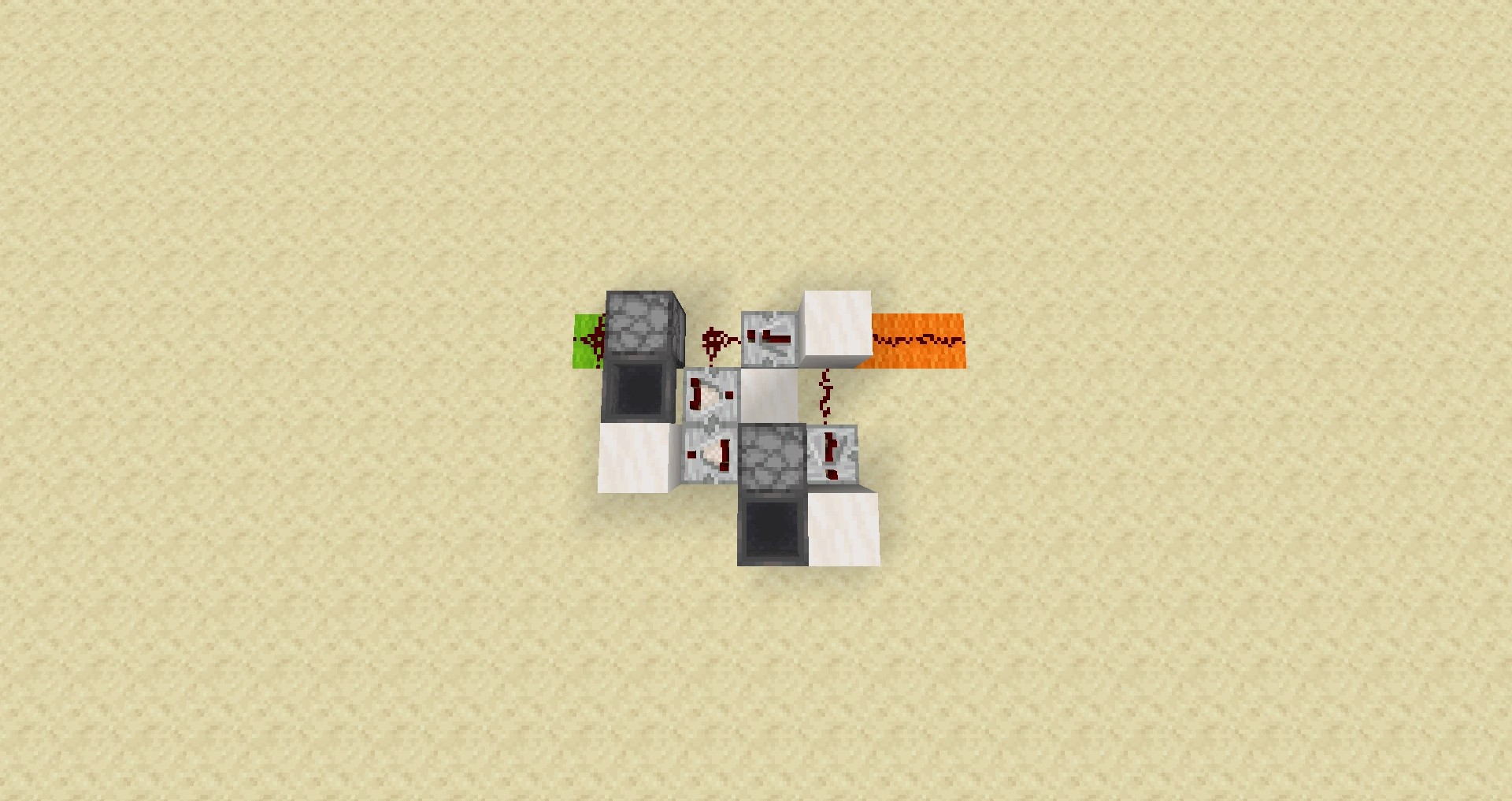
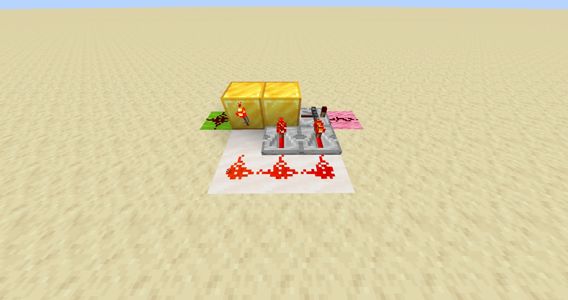
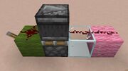
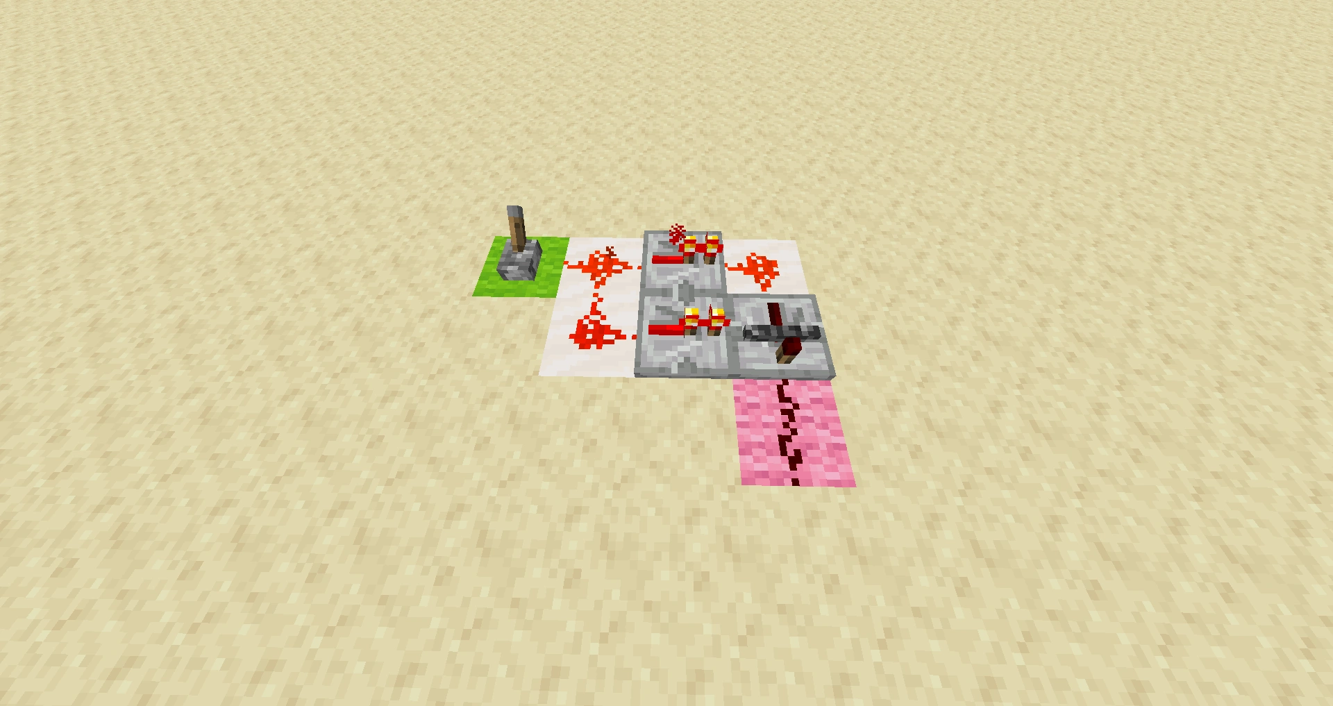
- Pulse length differentiator


Input at gray wool, short output at orange wool, long output at purple wool.
- A pulse length differentiator has two outputs and one input. Long pulses go through one output, while short pulses go to the other. It also keeps the tick length of the signals, which is why all the repeaters are set to one tick (i.e., a 1-tick signal remains a 1-tick signal). This is useful in a telegraph machine, in order to split up dashes and dots.
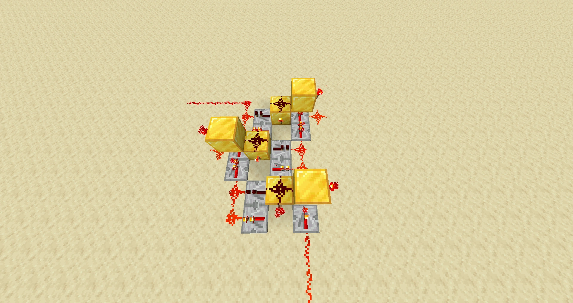
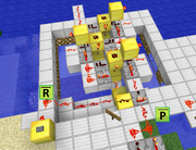
Transports and Logic gates implemented in Pulse logic[]
Some basic circuits exploiting the pulse logic. See the reference link for more advanced use of pulse logic circuitry.[14]
- Rail update transport
- 1-tileable
Typically, in pulse logic circuitry, signal is sent over Powered Rail or Activator Rail. Since the two don't propagate the updates to each other, this allows for tight tiling of modules.
- NOT gate
- 1-tileable
Negation of signal depends only on initial position of blocks, or often - only on interpretation of the signals by the creator.
- AND gate
- 1-tileable
- OR gate
- 1-tileable
The OR gate in pulse logic differs from AND gate only by initial positions of the blocks.
- XOR gate
- 1-tileable
Generic redstone OR in pulse logic acts as XOR.
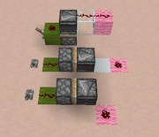
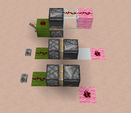
- Leaf block update transport
- 1-wide
The "greenstone" or "leafstone" transport depends on updates of leaf blocks depending on changing distance from the nearest log block. This transport is particularly helpful in transporting signal upward and downward. Updates do propagate to neighboring blocks though, and take 1 game tick to progress to next block. It makes it useful in creating 1 gametick resolution timing source though.
- Scaffolding block update transport
The Scaffolding propagates updates containing distance from supported scaffolding block. By moving a block under a suspended section of scaffolding, the player can send a signal an arbitrary distance upward and up to six blocks horizontally in any direction. The signal propagates at 1 block per redstone tick.
- Wall block update transport
- 1 tick regardless of distance, 1-tileable (see caveat)
Wall blocks (cobblestone wall etc.) instantly transmit signal arbitrary distance down by turning themselves and all wall block below from smooth wall segment to a pillar segment if certain blocks are placed on them or attached from a side. To form a smooth segment, a wall needs two other wall blocks or other blocks wall can attach to, adjacent to it from two opposite sides. If they are other wall blocks though, it doesn't matter if they are smooth or pillars - so the solution is 1-tileable, but requires uninterrupted columns of full blocks (or wall) on far ends. Probably the most practical way to toggle a wall between these states is a redstone-controlled trapdoor. The readout through an observer is possible only from below though, as the wall connects to an observer from a side.
References[]
- ↑ "RedsMiners" (4 September 2013). "Pulse multiplier 2.0" (Video). YouTube.
- ↑ "CarlitoxGamex" (7 January 2013). "Limitador de pulso Snapshot 1.5.2 / 1.5.1 con Redstone Comparator" (Video). YouTube.
- ↑ "NiceMarkMC" (3 May 2013). "Minecraft - Silent 1 Tick Pulse Generator" (Video). YouTube.
- ↑ "Goklayeh" (14 March 2013). "looking for Ver 1.5 pulse limiter designs" (Post #3). Minecraft Forum.
- ↑ "RamblinWreckGT" (29 March 2013). "Monostable Circuits and Sticky Pistons in 1.5.1" (Post #3). Minecraft Forum.
- ↑ "fennoman12" (27 May 2013). "Extremely small falling edge monostable | Redstone with Fenno" (Video). YouTube.
- ↑ "shufflepower" (22 May 2013). compact falling edge detector i created/ "A compact falling edge detector I created...". Reddit.
- ↑ "Redstone Sheep" (28 January 2013). "Super simple dual edge monostable" (Video). YouTube.
- ↑ ""Selulance" (16 April 2013). "Dual Edge Detector using locking repeaters" (Post #5). Minecraft Forum.
- ↑ "sfpeterm" (1 May 2013). flat dual edge detector extremely simple/ "Silent & Flat Dual Edge Detector [extremely simple]". Reddit.
- ↑ ""leetmoaf" (3 August 2013). believe what i made is a pulse limiter but im/ "I believe what I made is a pulse limiter. But I'm not 100% sure.". Reddit.
- ↑ "Cozzmy13" (1 June 2013). 3x1x2 pulse shortener/ "Small 3x1x2 pulse shortener". Reddit.
- ↑ "ImETtheAlien" (4 June 2013). "How to make simple compact fast redstone pulsers in Minecraft 1.5.2! [Tutorial] Works in 1.6!" (Video). YouTube.
- ↑ Pallapalla (2 December, 2017). "Observer logic: 1 Wide tillable logic gates + most compact adder?" (Video). YouTube.